Exhaust gas purifying apparatus for internal combustion engine

a technology of exhaust gas purification apparatus and internal combustion engine, which is applied in mechanical equipment, electrical control, machines/engines, etc., can solve the problems of insufficient change in the output of oxygen concentration sensor, inability to carry out conventional sub-feedback control, and deterioration of the precision provided by sub-feedback control

Inactive Publication Date: 2003-02-04
HONDA MOTOR CO LTD
View PDF17 Cites 6 Cited by
  • Summary
  • Abstract
  • Description
  • Claims
  • Application Information

AI Technical Summary

Benefits of technology

With this arrangement, feedback control is carried out by using the output of the upstream side detection means to correct the air-fuel ratio of the gas mixture so that it matches the target air-fuel ratio. And when the output of the downstream side detection means exceeds the predetermined value, the target air-fuel ratio is corrected in accordance with the output of the downstream side detection means, and further, at least until the output of the downstream side detection means exceeds the predetermined value, the target air-fuel ratio is corrected to obtain a smaller value than the stoichiometric air-fuel ratio. When the output of the downstream side detection means exceeds the predetermined value, it means that the hydrogen density at downstream of catalyst means disposed on the downstream side is high due to the water-gas reaction of the catalyst means. Therefore, only in this case, the target air-fuel ratio is corrected in accordance with the output of the downstream side detection means. As a result, correction of the target air-fuel ratio can be performed in accordance with a slight increase in the unburnt elements, and the density of the unburnt elements in the final exhaust can always be held low. In addition, at least until the output of the downstream side detection means exceeds the predetermined value, the target air-fuel ratio is set to a smaller value than the stoichiometric air-fuel ratio, so that a phenomenon can be prevented whereby there is an excessive increase in the oxygen contained in the exhaust and the NOx in the exhaust is increased. As a result, a preferable exhaust characteristic can be maintained.
The plurality of catalyst purifying means have a purifying function which reduce the density of the unburnt elements downstream of catalyst means disposed on the downstream side to several tens of ppm or lower. It is preferable that the downstream side detection means be an oxygen concentration sensor having a characteristic which varies the output thereof drastically in the vicinity of the stoichiometric air-fuel ratio.

Problems solved by technology

Then, when the hydrogen density is increased around the periphery of the oxygen concentration sensor, the sensor output is shifted to a density level that is lower than the actual oxygen density, and as a result, the precision provided by the sub-feedback control is deteriorated.
As a result, there is an insufficient change in the output of the oxygen concentration sensor, and the conventional sub-feedback control can not be carried out.
Therefore, a satisfactory change in the output voltage can not be obtained when the density of the unburnt elements is extremely reduced, and sub-feedback control can be difficult to carry out.
In this case, when the water-gas reaction is suppressed using the method shown in JP-A-8-31982, this problem can be partially resolved, but satisfactory effects can not be obtained.
According to this method, however, since the state of the exhaust finally discharged can not be confirmed, the exhaust characteristic may be degraded due to the deterioration of the catalyst located downstream of the oxygen concentration sensor.
And when a binary oxygen concentration sensor is employed, since it will not be able to detect when oxygen saturation of the catalyst in the oxygen storage capacity occurs nor when an excessive amount of oxygen is present downstream of the catalyst, the amount of NOx in the exhaust may be increased.

Method used


Image

  • Exhaust gas purifying apparatus for internal combustion engine
  • Exhaust gas purifying apparatus for internal combustion engine
  • Exhaust gas purifying apparatus for internal combustion engine

Examples


Embodiment Construction

The preferred embodiment of the present invention will now be described while referring to the accompanying drawings.

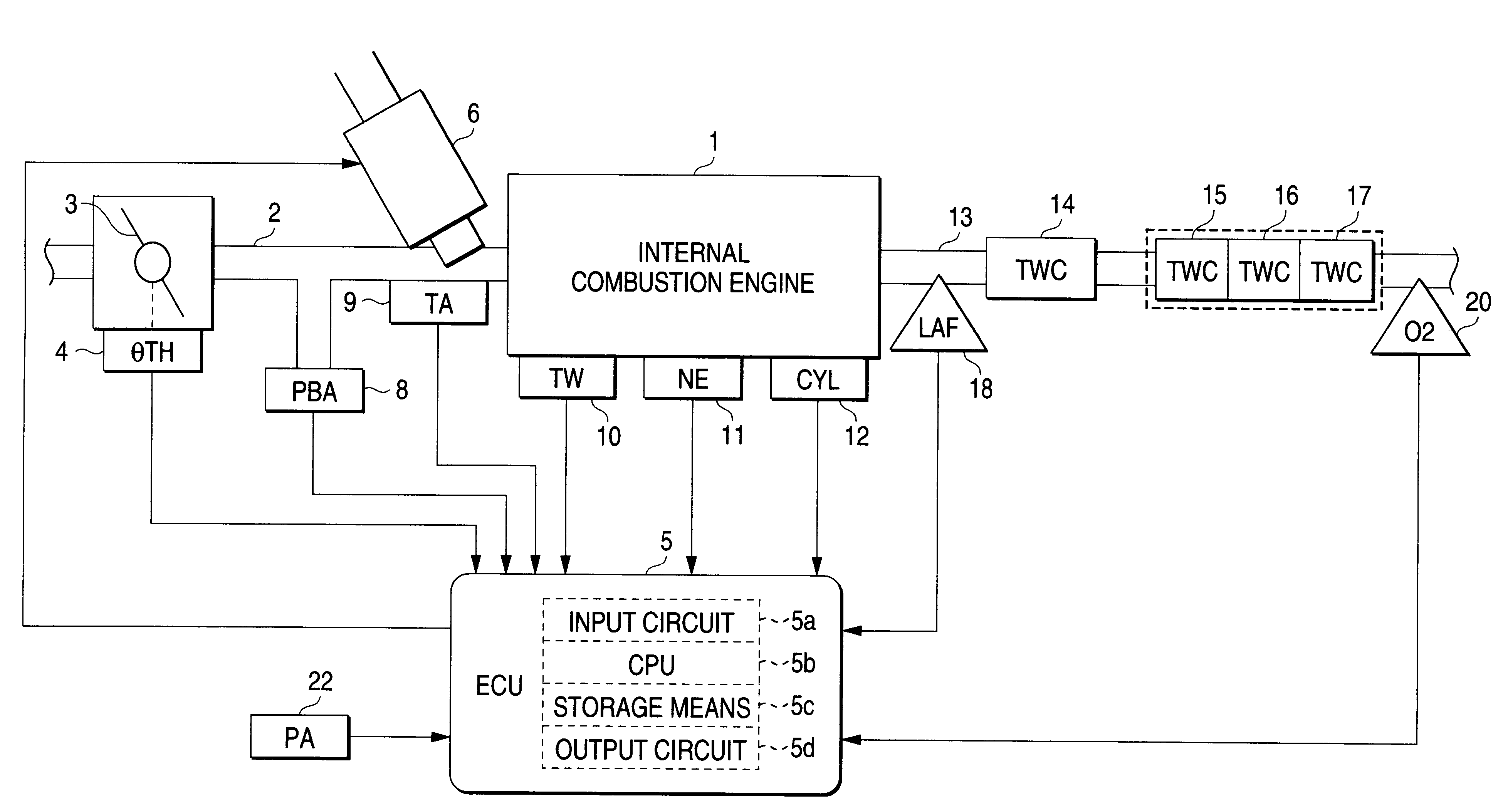
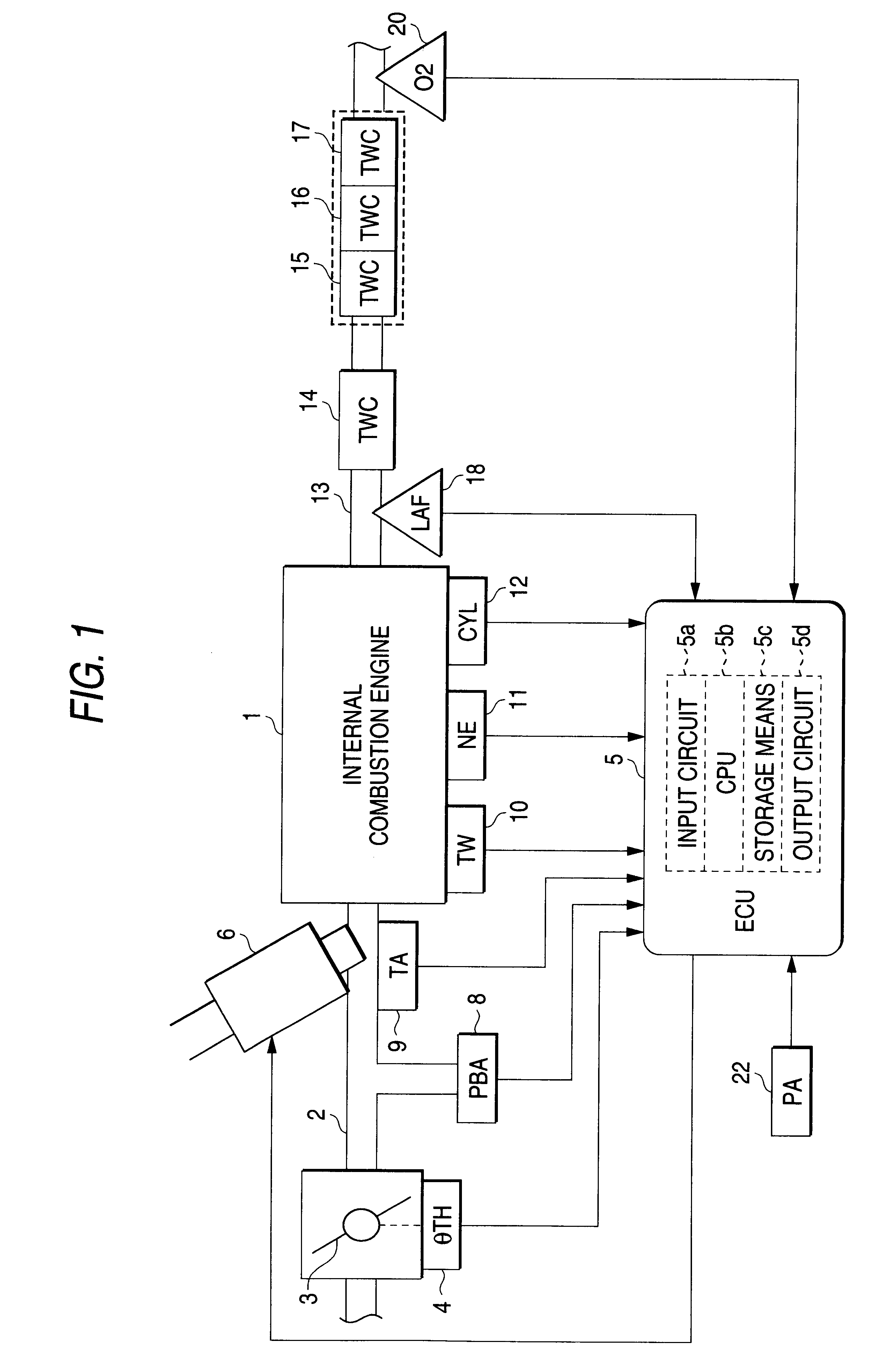
FIG. 1 is a diagram showing the general configuration of an internal combustion engine (hereinafter referred to as an engine) and an exhaust gas purifying apparatus according to the embodiment of the present invention. A throttle valve 3 is located along an intake pipe 2 of an engine 1 of, for example, four cylinders. A throttle valve opening (.theta.TH) sensor 4 is connected to the throttle valve 3. In accordance with the opening of the throttle valve 3, the throttle valve opening sensor 4 outputs an electric signal to an electronic control unit (hereinafter referred to as an ECU) 5 for controlling the engine 1.

For each cylinder, a fuel injection value 6 is located between the engine 1 and the throttle valve 3, and slightly upstream of an intake valve (not shown) in the intake pipe 2. Each fuel injection valve 6 is connected to a fuel pump (not shown) and is electric...


PUM


Abstract

In an exhaust gas purifying apparatus of the present invention, oxygen sensors 18 and 20 are respectively located upstream, a close coupled three-way catalyst 14 positioned at the upstream end of an exhaust system, and downstream, in a under floor three-way catalyst 17 positioned at the downstream end. When an output VO2 of the oxygen sensor 20 exceeds a predetermined voltage VO2H2, the first correction coefficient KCMDLS is calculated in accordance with the output VO2 (S12 and S13). And when VO2<=VO2H2 is established, in accordance with the engine operating state the second correction coefficient KVMDR is set to a predetermined value KVMDR0 that is slightly greater than 1.0 (S16 to S18), and the target air-fuel ratio coefficient KCMD is corrected by using the correction coefficients KCMDLS and KCMDR (S21).

Description

1. Field of the InventionThe present invention relates to an exhaust gas purifying apparatus, for which a plurality of exhaust gas purifying catalysts are provided, for purifying the exhaust gases from internal combustion engine, and relates in particular to an exhaust gas purifying apparatus that can reduce the density of the unburnt elements contained in the exhaust to several tens of ppm or lower.2. Description of the Related ArtIt is well known that unwanted elements in exhaust are reduced by providing, for an exhaust system, a plurality of three-way catalysts that perform the oxidation-reduction of elements (HC, CO and NOx) discharged by an internal internal combustion engine, and that when oxygen sensors are provided upstream and downstream of these three-way catalysts, the output of the upstream oxygen concentration sensor is employed to carry out main feedback control for adjusting the air-fuel ratio, and that the output of the downstream oxygen concentration sensor is emplo...

Claims


Application Information

Patent Timeline
Patent Type & Authority Patents(United States)
IPC IPC(8): F02D41/14F01N7/00F01N7/02F01N13/02
CPCF01N3/101F02D41/1441F01N13/009F01N13/0093Y02T10/22F02D41/1456Y02T10/12
Inventor SUZUKI, NORIOKITAMURA, TORU
Owner HONDA MOTOR CO LTD
Why Eureka
Try Eureka