
Cylindrical high voltage supercapacitor having two separators

a high-voltage supercapacitor and separator technology, applied in the direction of wound capacitors, fixed capacitors, transportation and packaging, etc., can solve the problems of slow release of energy in batteries and load consumption of peak power that can only be provided

Inactive Publication Date: 2003-01-21
LUXON ENERGY DEVICES CORP
View PDF20 Cites 60 Cited by
  • Summary
  • Abstract
  • Description
  • Claims
  • Application Information

AI Technical Summary

Benefits of technology

Accordingly, the present invention provides a cylindrical high voltage supercapacitor and a method of manufacturing the same, which employs a spirally winding method. Therefore, the cylindrical high voltage supercapacitor can be fabricated in a simple process.
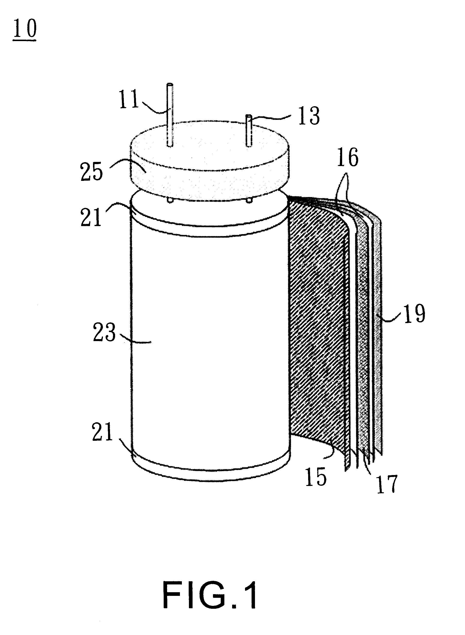
FIG. 1 shows the cylindrical high voltage supercapacitor and the method for manufacturing the same according to one embodiment of the present invention. In FIG. 1, a cylindrical bipolar supercapacitor 10 comprising three layers of electrodes 15, 17 and 19 and two separators 16 for separating each of the pairs 15, 17 and 17, 19 thereof is shown. The electrodes 15 and 19 are monopolar, that is, only one side of a current collector is coated with active material, wherein the current collector, shown together, serves as an electrode body of the electrodes 15, 17, and 19. The current collector is selected from a metallic foil such as an aluminum foil, a copper foil, a titanium foil or a nickel foil. The blank side of the current collector which is not coated with active material is insulated by fluorinated polymers, epoxy, acrylics, urethanes or silicones. By electrically insulating the blank side of the monopolar electrodes 15 and 19, additional separators thereon are not required. The less the separators used in a capacitor, the less quantity of the electrolyte is required. Where organic electrolyte is used in the supercapacitor, as the electrolyte is generally the most costly component, the reduced quantity of the electrolyte means that the cost of the capacitor is lowered.

Problems solved by technology

In applications in need of a large current in a short discharge time, the loads will consume a peak power that can only be provided by batteries with high power densities.
Batteries utilize slow chemical reactions that occur in the bulk of electrodes for energy storage, and the release of energy in batteries is equally slow.

Method used


Image

  • Cylindrical high voltage supercapacitor having two separators
  • Cylindrical high voltage supercapacitor having two separators
  • Cylindrical high voltage supercapacitor having two separators

Examples


example 2

Two 5.0V cylindrical supercapacitors C3 and C4 are prepared with the bipolar design is shown in FIG. 1, under the same conditions as Example 1, except that in this example, three electrodes, two monopolar and one bipolar, and an electrode area of about 40 cm.sup.2 are incorporated. Table 2 shows the electrical characteristics of the capacitors C3, C4 and a module in which the capacitors C3 and C4 are connected in parallel.

Since C3 and C4 have less than 1 / 3 the electrode areas of C1 and C2, and the former has a higher ESR, the capacitance of the capacitors C3 and C4 is much smaller than C1 and C2. As shown in Table 2, when C3 and C4 are parallel connected, that is, C3 / / C4, the capacitance of the module is equal to the sum of C3 and C4, while the ESR is about one half of C3 or C4. Different from Example 1 where the module of (C1+C2) is charged to 4.0V as a precaution, the parallel module (C3 / / C4) can be safely charged to 5.0V , 1.0V of increment, so that the module C3 / / C4 has more app...


PUM

PropertyMeasurementUnit
Electric potential / voltageaaaaaaaaaa
Capacitanceaaaaaaaaaa
Electrical resistanceaaaaaaaaaa

Abstract

A method of manufacturing a cylindrical high voltage supercapacitor. An anode and a cathode are provided. At least one bipolar electrode is interposed between the anode and the cathode, and a separator is intervened in each pair of the above electrodes. The anode, the cathode, the bipolar electrode and the separator, as placed in the above order, are wound concentrically into a roll, so as to form the cylindrical high voltage supercapacitor.

Description

SCENARIO OF THE INVENTION1. Field of the InventionThe present invention relates in general to a cylindrical high voltage supercapacitor and a method of manufacturing the same. More particularly, the invention relates to a spirally wound cylindrical high voltage supercapacitor with at least one bipolar electrode interposed between an anode and a cathode, and a method of manufacturing the same.2. Description of the Related ArtBatteries are always demanded for portable electronic devices, cordless power tools, uninterruptible power systems, and electric vehicles. There is a persistent trend that the batteries in the preceding applications should be compact, light, and high in energy-content. In order to meet these requirements, new electrode materials are explored and new cell designs are developed for batteries. Energy stored in batteries can be released in time periods from seconds to hours. When a long discharge time is needed, batteries require large energy densities that are gener...

Claims


Application Information

Patent Timeline
IPC IPC(8): H01G9/00H01G4/28H01G9/22H01G11/00H01G11/30H01G11/32H01G11/38H01G11/46H01G11/80H01G11/84H01G11/86
CPCH01G9/155H01G11/72Y02E60/13Y10T29/417Y02T10/7022Y02T10/70H01G11/34H01G11/46H01G11/62H01G11/60
Inventor SHIUE, LIN-RENWU, DIEN-SHICHAO, CHING-WENLI, LI-PINGHSIEH, MING-FANGCHUNG, HSING-CHENLO, WAN-TING
Owner LUXON ENERGY DEVICES CORP
Learn More