
Directed reflectors and systems utilizing same

Inactive Publication Date: 2003-01-14
OPTIDTECH OPTICAL IDENTIFICATION TECH
View PDF23 Cites 97 Cited by
  • Summary
  • Abstract
  • Description
  • Claims
  • Application Information

AI Technical Summary

Problems solved by technology

Nevertheless such microspheres typically have very poor lenticular quality, and as such lack a well defined focal length which is required by various reflector applications.
Furthermore, such microspheres are characterized by high level of optical aberrations which result in loss of the ability to focus incident light, particularly when incident at a wide range of acceptance angles, on the reflective layer.
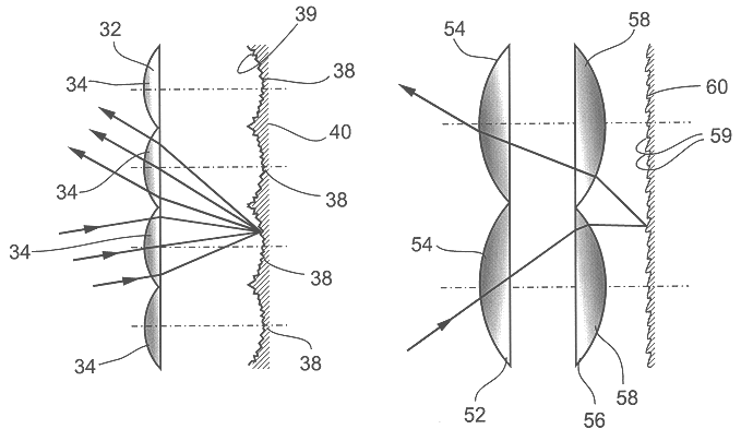
However, embedded lens array retroreflectors utilizing flat, specular (optically smooth) reflectors suffer from a limited range of incidence angles acceptable for retroreflection (also referred to in the art as acceptance angles).
In addition, when the reflecting surface is diffuse (optically rough or otherwise scattering) as specifically shown in FIG. 2b, this diffusely reflective surface of such prior art lens arrays also leads to scattering of the reflected light over several lenses, resulting in loss of retroreflected light and low retroreflection coefficient.
Although this limited angular response range and low retroreflection coefficient of prior art retroreflectors is acceptable for some applications, there are, however, applications for which these effects are non-tolerable.
In particular, applications which require accurate reflection of incident light, such as incorporation of retroreflectors in beam scanning applications, are extremely difficult to effect with arrays utilizing embedded microspheres; for these applications it is particularly important that the retroreflector and the light transmitter / receiver of the beam scanning apparatus are accurately aligned.
An array configuration with retroreflecting elements inclined at increasing angles to one another is, however, only suitable for use with a sector-shaped scanning beam.
Each individual retroreflector element must also be set at a predetermined position relative to the scanning beam and this makes it difficult, if not practically impossible, to manufacture such a retroreflector using cost-effective mass production techniques.
In addition, due to the functional design of cube-corner retroreflectors, fabrication or utilization thereof in sheeting results in the addition of undesirable thickness which limits their applicability.
While retroreflectors can and are manufactured by classical optical procedures (polishing, etc.), such devices are too expensive for most applications.
Retroreflectors manufactured by classical methods are high precision instruments of very high performance, but they are too expensive and often too bulky for most applications.
The standard molded / stamped retroreflectors of today and, more so, the bead suspension type of retroreflectors are inexpensive, but for many important applications their performance is, at best, marginal.
In practice, the lenslets in the arrays rarely satisfy the conditions of "thin lenses".

Method used


Image

  • Directed reflectors and systems utilizing same
  • Directed reflectors and systems utilizing same
  • Directed reflectors and systems utilizing same

Examples


example 1

Flicker Effect

Flicker, or intermittent reflection, is useful for attracting attention or for transmitting information. Low frequency flicker (0.2 to 10 Hz) is highly noticeable by the human eye and thus can be utilized to attract the attention of motorists and the like. Higher frequencies, 1 KHz and above, can be utilized for communication. Retroreflectors are inherently advantageous for such applications since they do not produce light and as such do not consume energy.

Direction Dependent:

Preferably flickering retroreflectors are entirely passive requiring no power source.

FIG. 10 illustrates a single cell of a multi-cell retroreflector according to any of the embodiments of the present invention described above. A plurality of such cells can be positioned, for example, on a road sign. As a vehicle on the road approaches the road sign, the illuminated point on the reflective layer 60 of the retroreflector moves as the vehicle moves towards the sign, since the angle of incidence on l...

example 2

Reflector Identifier Tags

As described in the prior art (see for example, U.S. Pat. Nos. 5,237,164 and 5,118,930) a simple retroreflector can be utilized as an identification tag. However, such prior art identifier tags suffer from several inherent limitations resultant from the retroreflectors utilized thereby.

Because of its superior light collection and reflection qualities the directed reflector of the present invention can be utilized in an identifier tag which would not suffer from the performance limitations characterizing prior art retroreflector identifier tags.

In general, retroreflector identification systems offer several advantages over other configurations, as follows: (i) simple light can be used for readout; unlike some radio or microwave based devices no potentially harmful radiation is generated or needed; (ii) identification of retroreflector provided codes can be effected from a distance of meters, instead of centimeters as in most other optical devices; and (iii) r...

example 3

Markings

Road Markings:

Retroreflectors are already used in several types of road markings, including traffic signs and lane marking. There are several advantages to using the reflectors of the present invention in road markings.

Since vehicle headlights are typically located lower than the driver's line of sight, retroreflectors are not the optimal solution for sign visibility, particularly for tall vehicles such as trucks. Signs that address truck drivers can benefit from non-retroreflecting directed reflectors, designed for the correct height difference and viewing distance. Directed reflectors can be designed such that a portion of the incident light is retroreflected, while the rest is reflected in an angle different than zero with respect to the incident light.

As already mentioned hereinabove the directed reflectors of the present invention can be designed to produce a flickering reflected light. Flickering light is currently utilized for turn and "hazard" signals in cars, for po...


PUM


Abstract

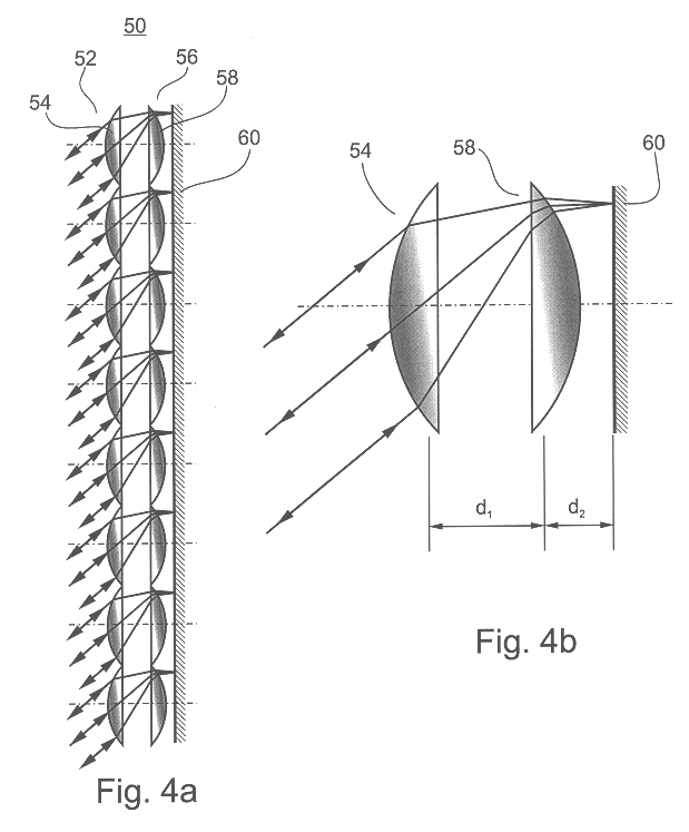
A wide angle directed reflector is disclosed. The directed reflector includes a lenticular layer including at least one array of lenslets, each of which having a focal length, The directed reflector further includes a reflective layer which is disposed relative to the lenticular layer. The lenticular layer and the reflective layer are constructed, designed and relatively disposed such that light incident at an angle of incidence on the lenticular layer is reflected by the reflective layer and redirected through the lenticular layer at a substantially constant angle relative to the angle of incidence.

Description

FIELD AND BACKGROUND OF THE INVENTIONThe present invention relates to a directed reflector, such as a retroreflector and more particularly to, directed reflectors which utilize an array of lenslets in combination with a reflector such that incident (incoming) light of a wide range of acceptance angles is reflected therefrom at a generally constant return angle relative to the angle of incidence.Directed reflectors are optical devices that reflect incident light in a direction which has an essentially fixed angle relative to that of an incident light beam, with little or no dependence on the angle between the light beam and the reflector surface. FIGS. 1a-c, show a directed reflection effect of a directed reflector 20. It is evident that, regardless of the angle of incidence of the incoming-light, the light is reflected at a constant angle with respect to the angle of incidence (.DELTA..alpha.).Retroreflectors are directed reflectors which redirect light towards its originating sourc...

Claims


Application Information

Patent Timeline
IPC IPC(8): G02B3/00G02B5/13G02B5/12
CPCG02B3/0056G02B5/13G02B3/0062G02B26/02
Inventor EISENBERG, NAFTALI P.GLASER-INBARI, ISAIADRORI, AVISHAIKAROUBI, REOUVENARIELI, YOEL
Owner OPTIDTECH OPTICAL IDENTIFICATION TECH
Learn More