
Polishing machine

A polishing machine and tool holder technology, applied in the polishing machine field, can solve the problems of low work reliability and the like

Inactive Publication Date: 2005-07-20
FINEACETECH
View PDF0 Cites 21 Cited by
  • Summary
  • Abstract
  • Description
  • Claims
  • Application Information

AI Technical Summary

Problems solved by technology

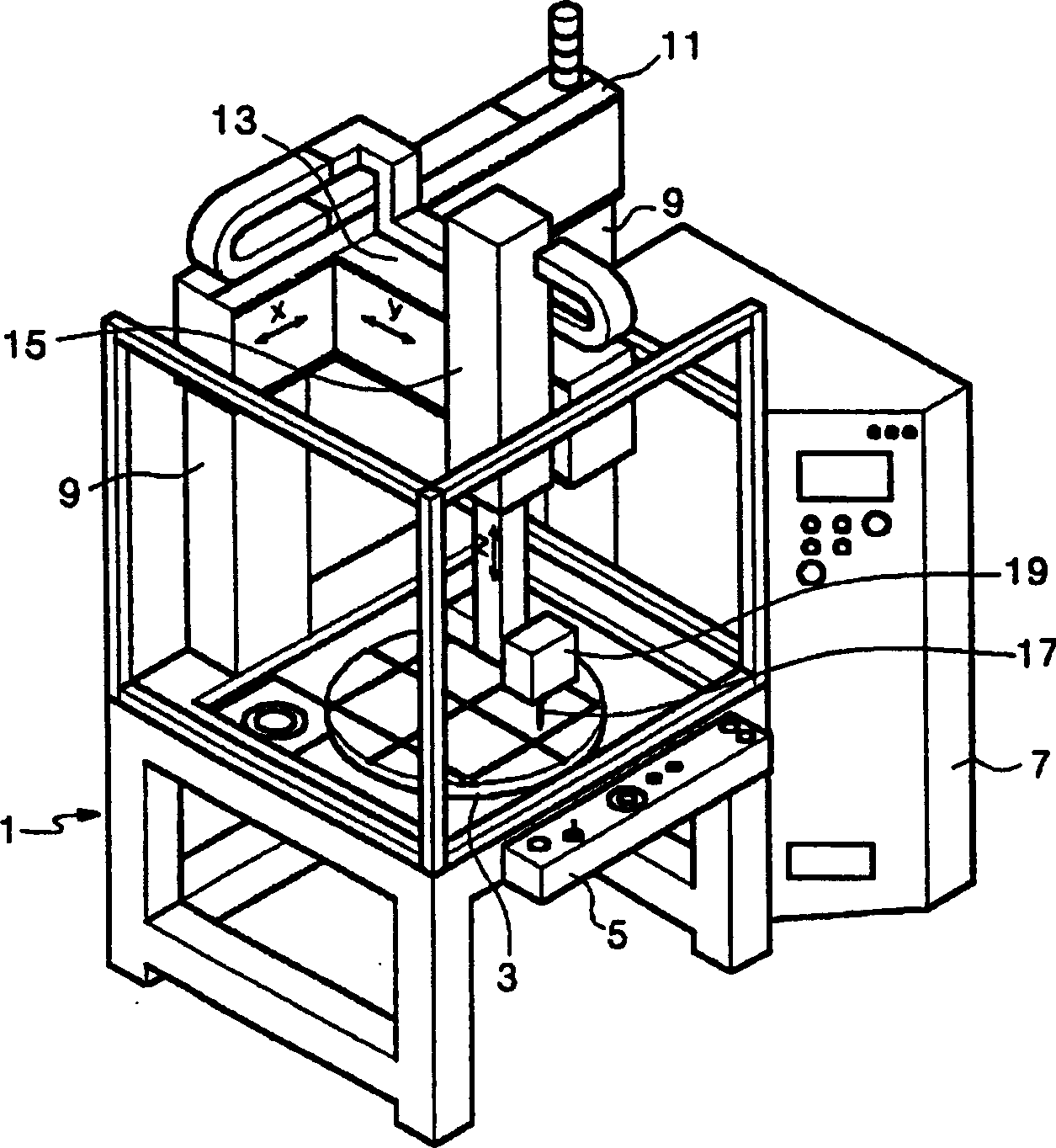
However, because conventional machine tools are not equipped with devices to maintain stable pressure, the work reliability is low

Method used


Image

  • Polishing machine
  • Polishing machine
  • Polishing machine

Examples


Embodiment Construction

[0026] Hereinafter, preferred embodiments of the present invention will be described in detail with reference to the accompanying drawings.

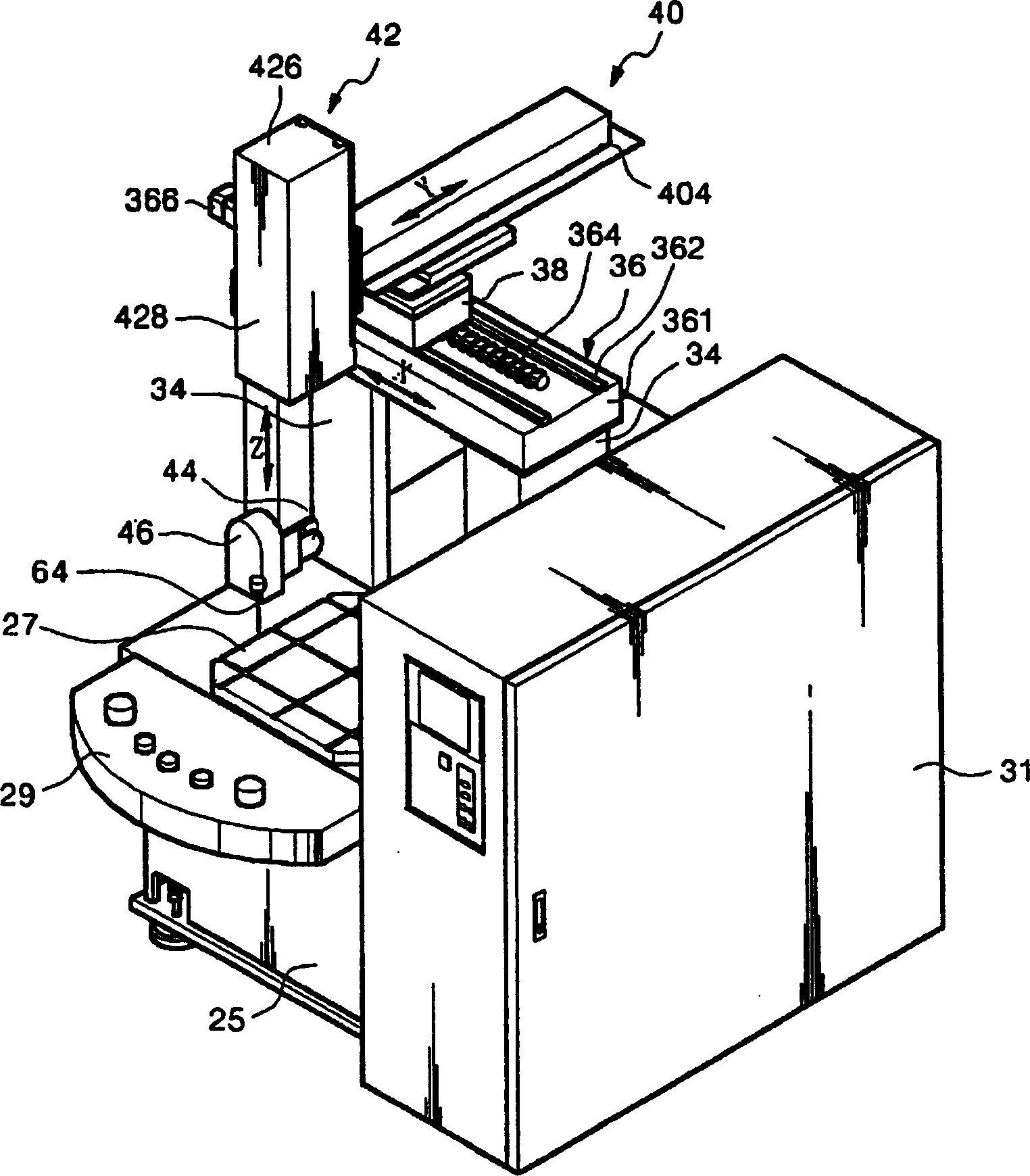
[0027] First, if figure 2 As shown, the polishing machine according to the preferred embodiment of the present invention includes a main body 25 provided with a support portion and a table 27 mounted on the main body 25 so as to rotate at a predetermined angle. The workpiece is fixed on the workbench 27 .

[0028] Furthermore, in the main body 25, a control unit 29 having various operation switches and buttons manipulated by the user to control all operations of the machine and a control box 31 for receiving information from the control unit 25 are equipped. Unit 29 and output control signals to various operating units.

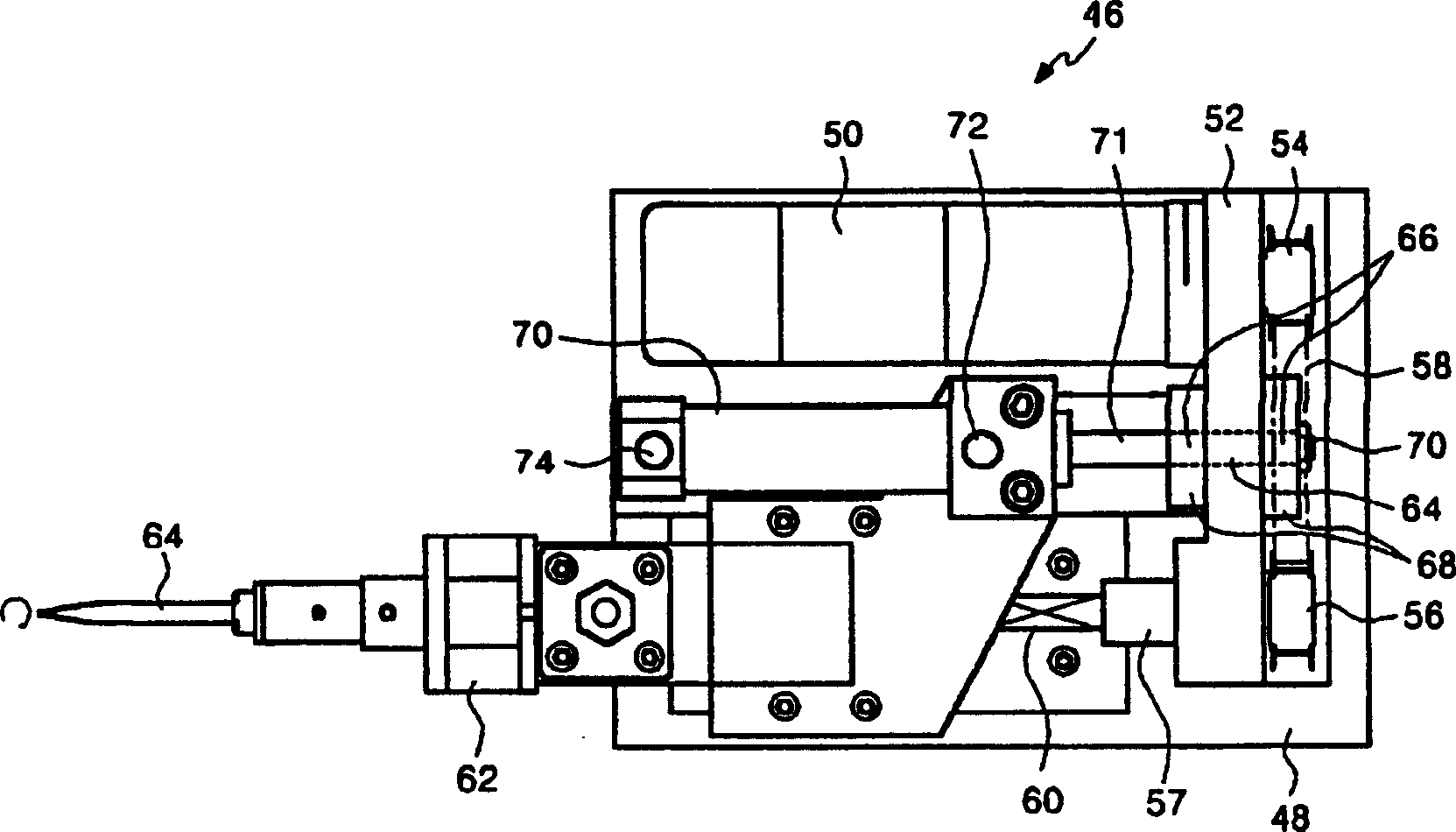
[0029] A pair of cylinders 34 having a rectangular rod shape are fixed on both sides of the main body 25 . On the column body 34, a first conveying unit 36, a conveying block 38 and a second conveying unit 40 are ar...


PUM


Abstract

The polishing machine processes a workpiece put on table of body by four-directional control and is provided with a pair of columns. It comprises: first carrying unit having both ends fixed to pair of columns and having carrying part mounted on upper side; a second carrying unit being fixed to the carrying part in the direction orthogonal to the first carrying unit; third carrying unit being fixed to one end of the second carrying unit in the direction orthogonal to the second carrying unit; a tool head unit being mounted to lower side of the third carrying unit to be inclinable at predetermined angle by a tilting unit rotating at a constant angle and having driving means for rotating a polishing tool mounted at one side; and automatic constant pressure regulating means providing a predetermined virtual pressure with respect to the polishing tool mounted on the tool head unit.

Description

technical field [0001] The present invention relates to a polishing machine, and more particularly to a polishing machine capable of improving the processing accuracy of workpieces and its reliability, which uses abrasive tools to perform polishing processing at a constant pressure through a static pressure system, and in a more stable manner to control the operating system of the tool transport unit. Background technique [0002] Typically, polishing processes are used to polish portions of the surface of castings of various shapes and patterns (eg, moldings, cold-forged moldings, and blank moldings) to mirror-smoothness. [0003] In order to smooth the surface and maintain surface precision, the polishing process works in terms of minimizing the surface roughness after the grinding or lapping process. [0004] Due to more diverse consumer demands, equipment such as home appliances and OA (office automation) devices tend to have a shorter life cycle, and the need for molds...

Claims


Application Information

Patent Timeline
Patent Type & Authority Applications(China)
IPC IPC(8): B24B47/20B24B19/26B24B27/00B24B41/02
CPCB24B27/0046B24B19/26B24B41/02B24B47/20
Inventor 尹祥大
Owner FINEACETECH
Learn More