
Exhaust gas recovery method and apparatus

a gas recovery and exhaust gas technology, applied in the direction of positive displacement liquid engine, liquid degasification, separation process, etc., can solve the problems of large amount of water needed for scrubbers, high cost of active carbon replacement, and high deterioration rate of active carbon

Inactive Publication Date: 2002-11-05
FUJIFILM HLDG CORP +1
View PDF8 Cites 14 Cited by
  • Summary
  • Abstract
  • Description
  • Claims
  • Application Information

AI Technical Summary

Benefits of technology

This method enables efficient recovery and reuse of volatile organic compounds with reduced operational costs and minimal waste water generation, effectively addressing the limitations of existing technologies by leveraging the difference in boiling points for efficient separation.

Problems solved by technology

However, in this method, because some types of volatile organic compounds, for example, solvent gases, cannot be adsorbed by an adsorbent, they are released into the atmosphere.
Also, there are cases in which, with respect to some types of volatile organic compounds, the deterioration rate of the active carbon is high.
In such cases, a problem arises in that the cost for replacing the active carbon (running cost) becomes high.
However, in a case where the volume of gas is large and the concentration of the volatile organic compound gas is small, a large amount of water for the scrubber is needed.
In this case, because the amount of water for the scrubber is large, a large amount of waste water, which includes the volatile organic compound recovered from the scrubber, is generated.
Accordingly, this method is not economical.
In the fourth process, because the concentration of the volatile organic compound in the water is high, the amount of the water which is subjected to this separating process is small, therefore, a low level of energy is needed for this separating process.

Method used


Image

  • Exhaust gas recovery method and apparatus
  • Exhaust gas recovery method and apparatus

Examples


Embodiment Construction

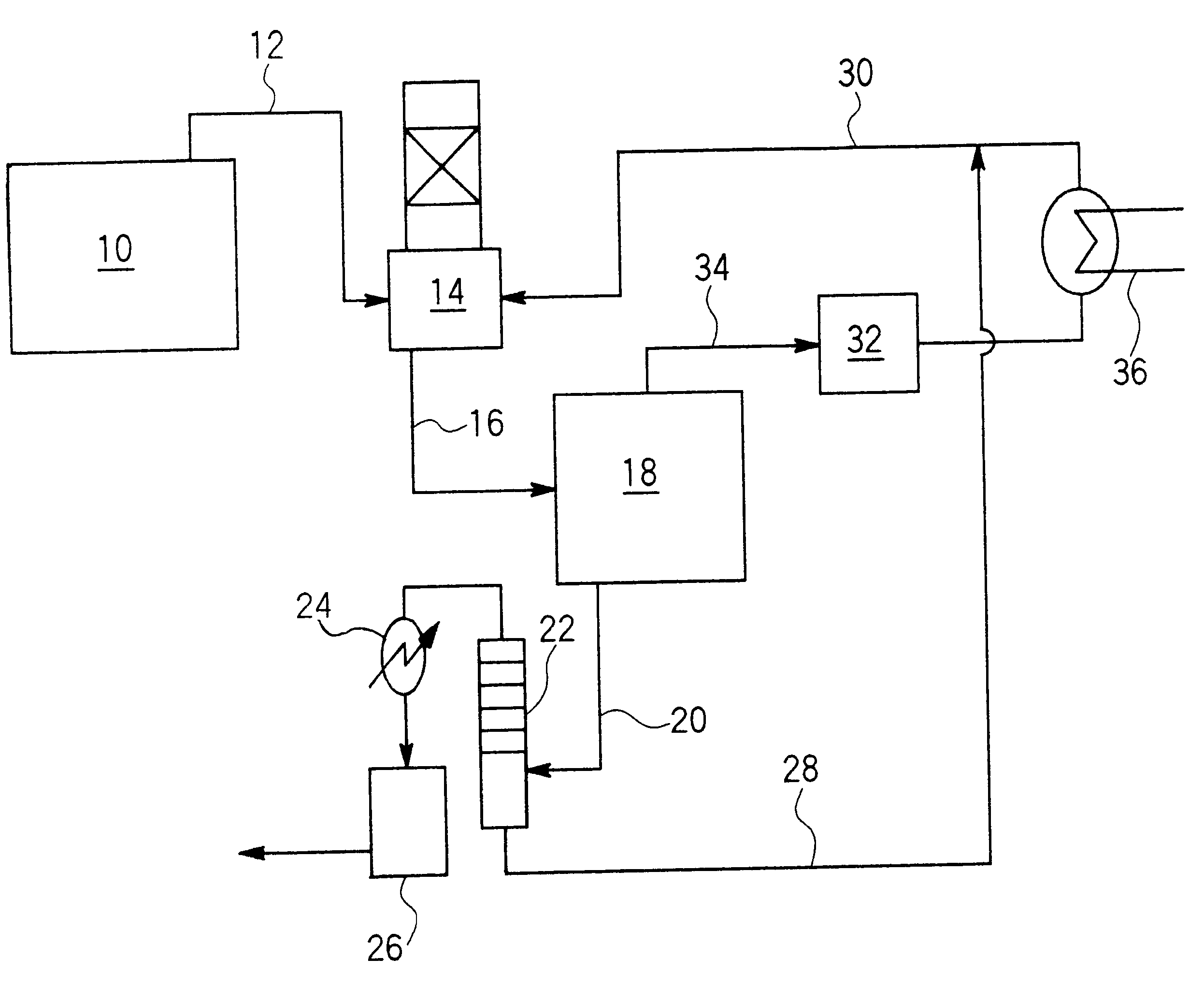
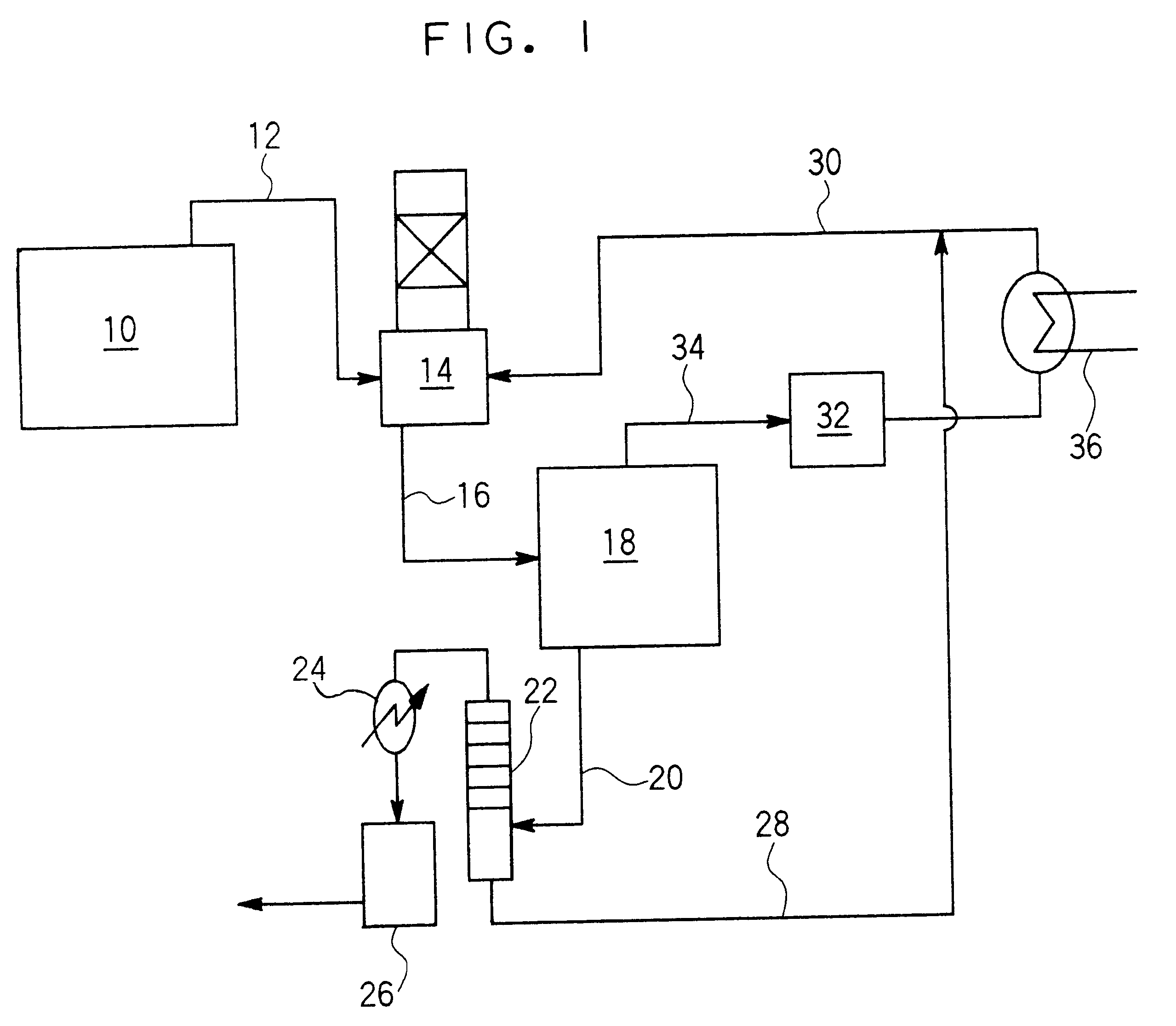
Methanol was recovered from an exhaust gas containing methanol exhausted from the solvent exhaust gas discharging source 10.

The exhaust gas containing the methanol was introduced into the spray tower 14 at a rate of 2000 Nm.sup.3 / min. The amount of methanol contained in the exhaust gas was 500 ppm. When water was sprayed from the top portion of the spray tower 14 and the exhaust gas was introduced into the lower portion of the spray tower 14, the methanol concentration of the water obtained from the spray tower 14 was 5000 ppm.

Next, the water, which was obtained from the spray tower 14 and whose methanol concentration was 5000 ppm, was introduced into the freezing and concentrating device 18 at a rate of 200 T / day, and the freezing and concentrating process was carried out by the freezing and concentrating device 18. As the result, concentrated water, whose methanol content was 90000 ppm, was obtained at a rate of 10 T / day. Also, ice (ice crystal grains and ice grain aggregates), w...


PUM

PropertyMeasurementUnit
volatileaaaaaaaaaa
concentrationaaaaaaaaaa
volumeaaaaaaaaaa

Abstract

An exhaust gas recovery method and apparatus including: a first process in which volatile organic compound gas in exhaust gas from a exhaust gas discharging source is absorbed into water by a scrubber; a second process in which water including the volatile organic compound, which is obtained in the first process, is frozen and the volatile organic compound herein concentrated such that the water including the volatile organic compound is separated into water including a high concentration of the volatile organic compound, level of concentration being higher than that of the water including the volatile organic compound which is obtained in the first process, and ice; a third process in which cold of the ice obtained in the second process is used; and a fourth process in which the water including a high concentration of the volatile organic compound, which is obtained in the second process, is reused, is provided.

Description

1. Field of the InventionThe present invention relates to an exhaust gas recovery method and apparatus. In particular, the present invention relates to an exhaust gas recovery and reuse method and apparatus, in which a volatile organic compound, such as a solvent, in the exhaust gas is recovered and reused.2. Description of the Related ArtA volatile organic compound gas, such as a solvent, is generated from a factory. It is preferable that the gas is recovered and reused. Various methods of recovering the solvent and the like are proposed. Absorbing a volatile organic compound by an adsorbent such as active carbon is generally known as a conventional method of recovering a volatile organic compound exhausted from a factory or the like. However, in this method, because some types of volatile organic compounds, for example, solvent gases, cannot be adsorbed by an adsorbent, they are released into the atmosphere. Namely, with respect to the some kinds of the volatile organic compounds,...

Claims


Application Information

Patent Timeline
Patent Type & Authority Patents(United States)
IPC IPC(8): B01D53/14B01D8/00B01D53/44B01D53/18B01D53/34B01D53/77C02F1/22
CPCB01D8/00B01D53/14B01D2257/704Y02A50/20
Inventor HAYASHI, KENJINAGATA, JUNICHIFUNABASHI, SHINICHI
Owner FUJIFILM HLDG CORP
Learn More