
IC socket and IC tester

a technology of ic socket and ic tester, which is applied in the direction of measuring instrument housing, coupling device connection, instruments, etc., can solve the problems of test failure, deterioration in production, and failure of the tube assembly 18 to return to its original position,

Inactive Publication Date: 2002-10-15
ADVANTEST CORP
View PDF10 Cites 139 Cited by
  • Summary
  • Abstract
  • Description
  • Claims
  • Application Information

AI Technical Summary

Benefits of technology

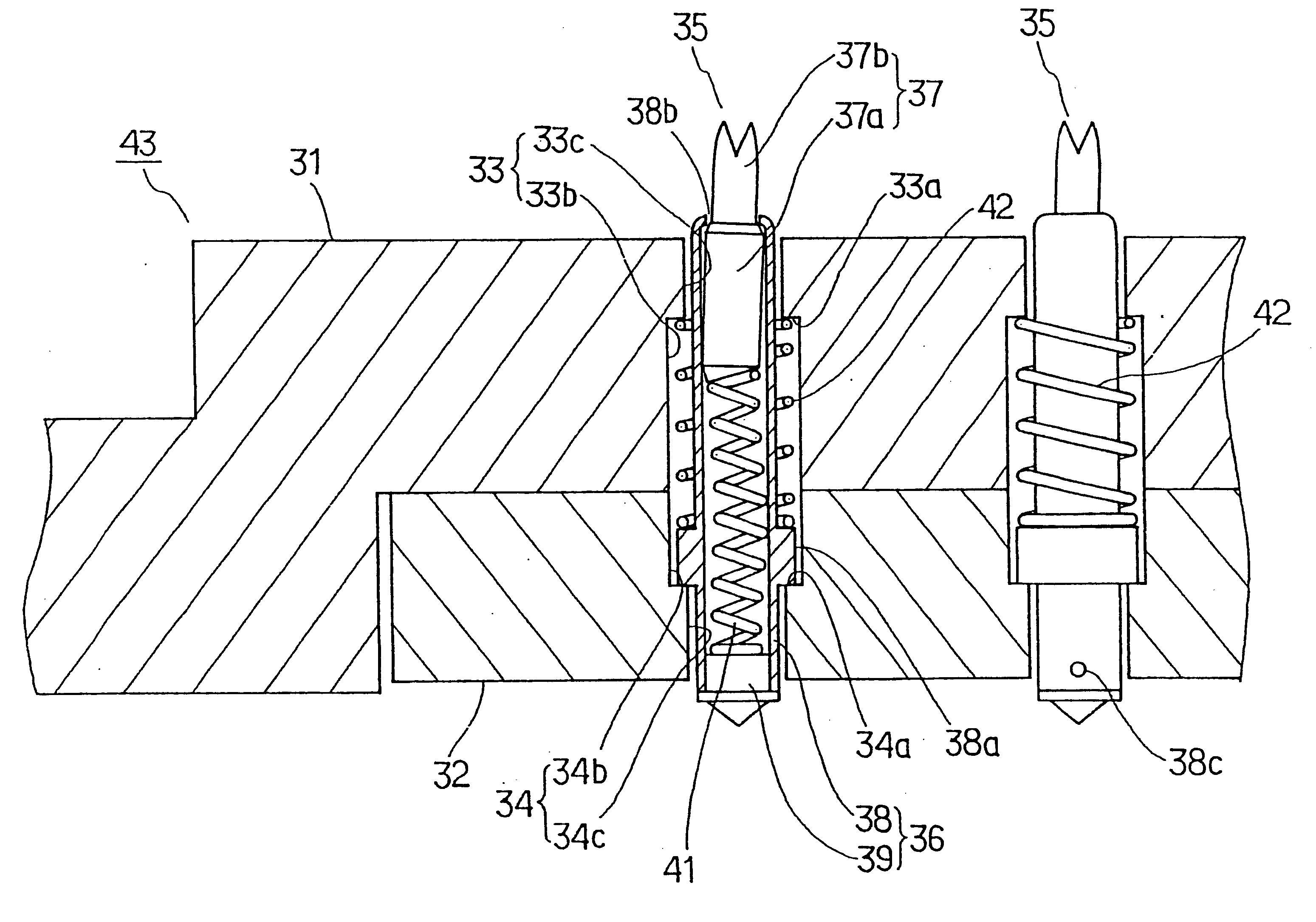
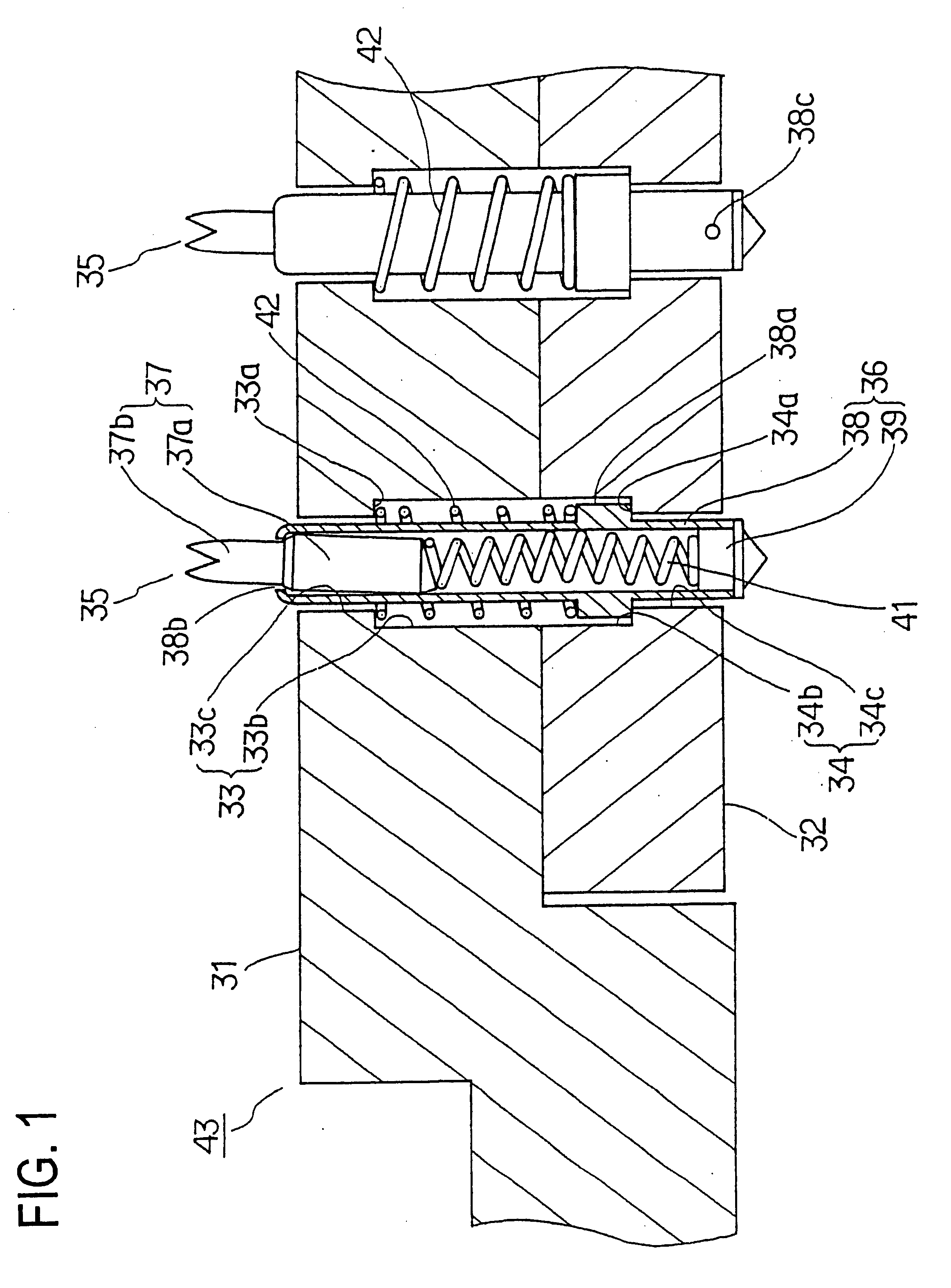
FIG. 1 is a view illustrating, in cross-section, a principal part of a preferred embodiment of the IC socket according to this invention;
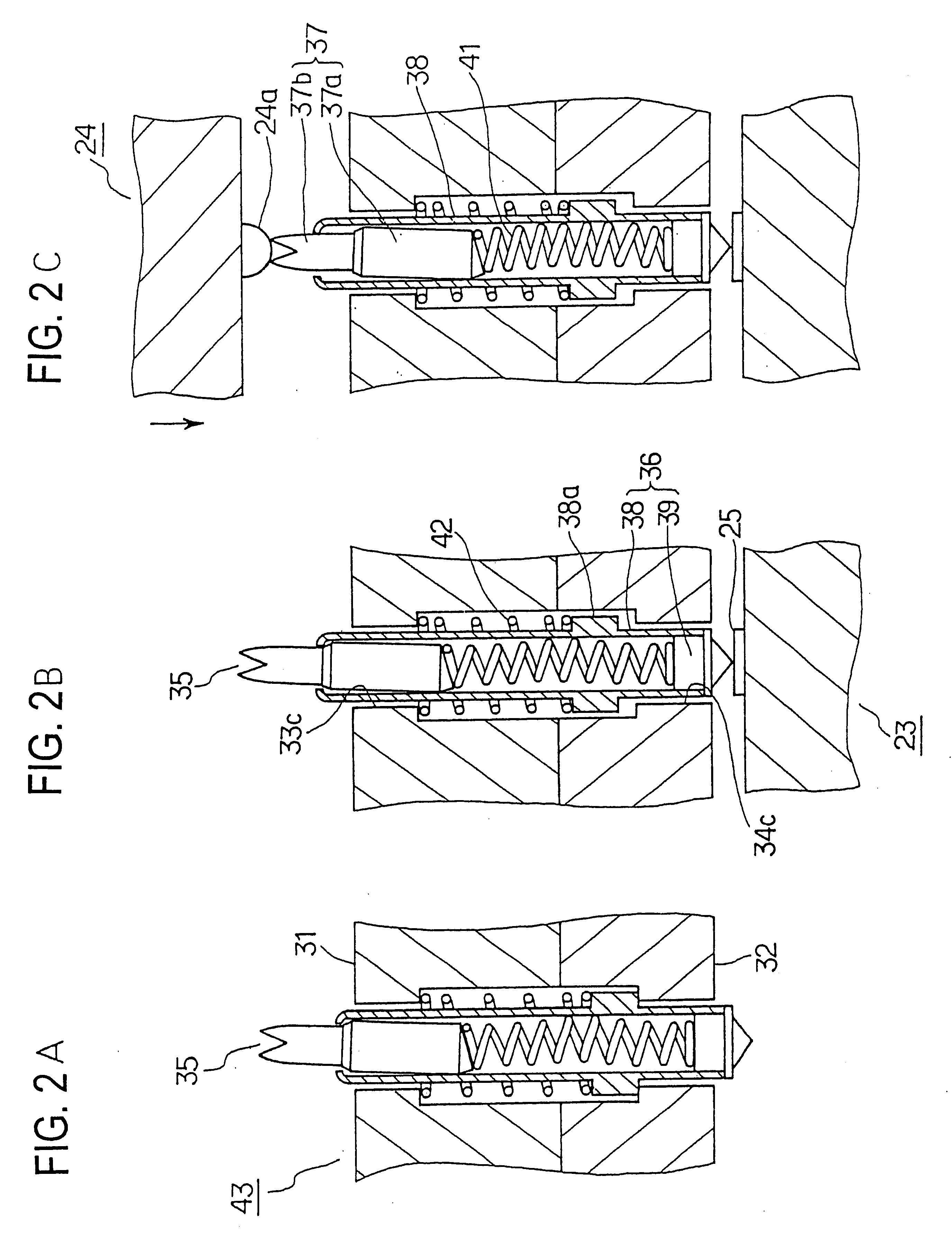
FIG. 3 is a view illustrating how the probe pin of another embodiment of the IC socket according to this invention works;
FIG. 4 is a view schematically illustrating the arrangement of the IC testing apparatus according to this invention;

Problems solved by technology

However, the thus constructed IC socket 1 has often encountered a situation in which the tube assembly 18 fails to return to its original position even though the device 24 under test has been removed.
Occurrence of such contact failure results in a test failure.
In addition, since even the retesting cannot insure that such failures distinguished one from the other, it leads to a deterioration in production.
For this reason, the failure of the tube assembly 18 to return to its original position has become a serious problem.
Hence, the slide surfaces of the tube 14 are machined surfaces having rather poor surface roughness, so that those surfaces will scratch or abrade the opponent slide surfaces of the housing 13 and bottom cover 21 and produce wear debris which will accumulate in gaps between the tube 14 and the through-apertures 19, 22, resulting in poor slidability.

Method used


Image

  • IC socket and IC tester
  • IC socket and IC tester
  • IC socket and IC tester

Examples


Embodiment Construction

The invention will be described in details with reference to the accompanying drawings. FIG. 1 is a view illustrating, in cross-section, the details of the principal part of a preferred embodiment of the IC socket according to this invention. The housing 31 and the bottom cover 32 have through-apertures 33 and 34, respectively formed therethrough in an array corresponding to that of terminals of a device to be tested. The housing 31 and the bottom cover 32 are integrally secured together with their through-apertures 33 and 34 being in opposed alignment with each other. It should be noted that the exterior appearance of the housing 31 is similar to that of the housing 13 shown in FIG. 5.

Fixation of the bottom cover 32 to the housing 31 is effected, with probe pins 35 accommodated and held in place in the through-apertures 33, 34, as by screws not shown in FIG. 1. These housing 31 and bottom cover 32 may be made of resin. It is also to be noted that the through-apertures 33 and 34 are...


PUM


Abstract

A housing and a bottom cover are secured together and have pairs of aligned through-apertures, and probe pins are accommodated in respective pairs of through-apertures to provide an IC socket. Each probe pin comprises a tube having a stop flange formed around its outer periphery, a movable plunger accommodated in the tube such that an extension portion of the movable plunger in urged to project out of a narrowed first end portion of the tube by a first coil spring, and a fixed plunger fitted to a second end portion of the tube. Each probe pin is urged by a second coil spring such that the stop flange on the tube is urged into abutment with a shoulder portion of a through-aperture of the bottom cover, whereby a tip end of the fixed plunger is projected beyond the outer surface of the bottom cover and a tip end of the movable plunger is projected beyond the outer surface of the housing.

Description

This invention relates to an integrated circuit (IC) testing apparatus, and more particularly to the construction of an IC socket onto which semiconductor devices being tested (ICs being tested) are to be placed for electrical connection and which is superior in the contact stability.THE BACKGROUND ARTFIG. 5 is a schematic view illustrating the exterior appearance of a prior art IC socket of this type, and FIG. 6 shows the details of the construction thereof. The IC socket 11 comprises a plastic housing 13 in which a number of probe pins 12 are carried. In the illustrated example, the IC socket 11 is adapted to accommodate CSPs (Chip Size Packages) such as BGA (Ball Grid Array) and has a grid array of several tens of probe pins 12. It is to be understood that in FIG. 5 the probe pins 12 are symbolized to illustrate only the positions of the array of the pins.As shown in FIG. 6, each of the probe pins 12 comprises a metallic tube 14, a fixed plunger 15 integrally fixed to the tube at...

Claims


Application Information

Patent Timeline
IPC IPC(8): G01R1/067G01R1/073H01R13/24H01R13/22G01R1/02G01R1/04
CPCG01R1/07371H01R13/2421G01R1/06722G01R1/0483H01R2201/20H01R12/714G01R1/0466H01R33/76
Inventor WATANABE, FUMIOTAKESHITA, SATOSHI
Owner ADVANTEST CORP
Learn More