
Ophthalmic lens synthesized from its specification

a technology of ophthalmology and specification, applied in the field of new prescription lenses, can solve the problems of limited shape and material availability, limited vision, and limited vision, and achieve the effects of optimizing the manufacturing process, reducing diffraction aberrations and image blur, and reducing vision impairmen

Inactive Publication Date: 2002-10-15
GIL THIEBERGER
View PDF5 Cites 110 Cited by
  • Summary
  • Abstract
  • Description
  • Claims
  • Application Information

AI Technical Summary

Benefits of technology

It has been discovered that if we want the Add-on type to be very thin, have very good optical qualities and acceptable bond, the lens' surface and the eyewear's surface have to be initially matching. As the Add-on type will initially fit to the eyewear's surface more closely, it will have less aberrations, will be thinner, will bond better and will be less visible to the wearer and observers.
Method #6: When the former methods are not sufficient, we can make a special converting layer which will be called herein "the universal converter". The universal converter can adapt between any Add-on Thieberger-design-lens to any eyewear surface. The macroscopic shape of the universal converter is designed such that one of the surfaces is initially matching to the eyewear, and the other surface is initially matching to the Add-on Thieberger-design-lens. The microscopic structure of the universal converter is designed such that it will imitate the original eyewear which the Add-on was designed to, and cancel the aberrations caused by the non-matching eyewear and the converter. The universal converter is a very power tool because it enable us to convert, with only one converting layer, a whole kit of Add-on Thieberger-design-lenses which is adapted to a specific eyewear, to be adapted to another eyewear and / or different pupil location.

Problems solved by technology

When a well eyesight person wants to use any eyewear, he is limited only by the industry wide availability of eyewear shapes and materials.
When a person suffers from visual impairment wants to use any eyewear, not only he is limited by the industry wide availability of eyewear shapes and materials but he is limited also by the industry availability of prescription eyewear, which has limited shapes and materials available.
Until now, a method, having very good results, that converts any unprescription eyewear to a prescription one was not available.
As a result, people suffer from visual impairment had to use prescription glasses or a combination of thick prescription lenses and a big eyewear instead of using any eyewear they want.
On the contrary, prescription eyewear designers are seriously limited by the shape and thickness of prescription lenses, therefore, their creativity is restricted and not exploited appropriately.
Until now, a method, having very good results, that enable to form a prescription lens in any shape and almost any thickness the designer wants was not available.
Shaping and cutting those lenses require expensive tools which are not accessible to most of the people.
As a result, most of the people don't have unique eyewears.
The industry does not consider it practical to prefabricate a stock of lenses having every possible power of each parameter in every possible combination that may be needed.
Grinding or molding such lenses to meet the specifications of a particular prescription requires costly equipment, highly skilled technicians and is time consuming.
The fabrication of laminated lenses is subject to certain problems which have not heretofore been adequately addressed and resolved.
The layers are available in a very limited amount of shapes and are not designed to bond to an eyewear that has surface that is not spherical or toric.
In addition, The laminated lenses are usually frailer than regular lenses and elastic laminated lenses are not available.
The problem with Modem Fresnel lenses is that they are limited to flat or rotationally symmetric surfaces.
As a result, there were optical imperfections and distortions and aberrations visible to the wearer.
The planarly smooth Fresnel lens does not readily adhere to curved surfaces on a permanently basis and was susceptible to trapping bubbles between a base surface and itself.
Shirayanagi do not disclose how to produce a prescription lens that can have any desired shape and / or synthesis from its specifications, do not disclose laminated lenses, do not disclose elastic lenses, do not disclose lenses which are too thin to provide a desirable degree of impact strength, do not disclose lenses that adhere to an eyewear, do not disclose lenses which can be cut using simple cutting accessories, do not disclose protected lenses, and do not disclose a method that controls on the viewed geometric pattern made by the Fresnel lens.
Difficulty of manufacture represents another shortcoming of diffractive lenses since the diffractive surface must be in tolerance on the order of the wavelength of light.
But the result is poor, as Dauvergne states in the patent "The proposed eyewear is not considered a substitute for prescription lenses, but is an auxiliary item that is preferably tinted and styled to provide an attractive appearance."
The main problem with those patents is that the final prescription lenses are smooth, i.e., no surface jump discontinuities and no discontinuous changes in the surface slope.
As a result, those lenses are thick and can have a very limited amount of shapes because of the connection between the macroscopic shape of the optical article to its optical characteristics
According to that patent, the organic layer is limited to the purpose of correcting the aberrations of the glass lens.
The problem of the connection between the macroscopic shape of the optical article to its optical characteristics strikes mirror designers too.
Mirror designers are seriously limited by the shape of the mirror, therefore, their creativity is restricted and not exploited appropriately.
For instance, vehicle manufacturers spend huge percents of their development budgets on impressive designs, but concerning to mirrors, all of them are forced to use the same flat mirror.
Prior art unifocal and multifocal Fresnel mirrors are limited to flat or rotationally symmetric surfaces.
Prior art mirrors construct of plenty of microscopic spherical lenses suffers from blurred image.

Method used


Image

  • Ophthalmic lens synthesized from its specification
  • Ophthalmic lens synthesized from its specification
  • Ophthalmic lens synthesized from its specification

Examples


example # 2

EXAMPLE #2

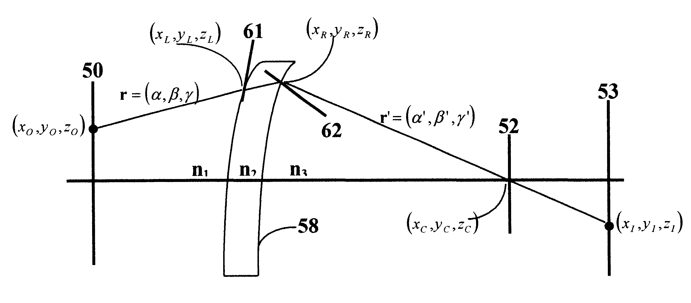
The normals to the surface can be calculated by using one of the well know in the art models of astigmatic human eye. Referring to FIG. 20, the locations of all the system parts (i.e., the object 50, the corrective eyewear lens 58, and model of the astigmatic eye 70) are known. The desired image (of the object) on the retina is known from the eye model. The defocus blur image formed by the astigmatic eye (without corrective lens 58) on the retina is known from the eye model. By using Ray-tracing technique, and taking in account the movements of the eye, we can calculate the required microscopic normals of the corrective lens 58 so that the astigmatic effect of the corrective lens optimally cancels the astigmatic effect of the eye, and by that, the desired image will be formed on the retina.

The distances of the object from the eye determine the corrective lens type. For unifocal lens, the object distance is the same over the entire field of view. For multifocal and progress...

example # 3

EXAMPLE #3

There are many more possibilities to solve the well know mathematics problem of obtaining a surface from its normals (step #9). For example, each saw-tooth can be calculated by using iterative algorithms of high order polynomials with continuous partial derivatives at the boundaries (between the normals). Each saw-tooth can be smoothed through spline analysis or technique in such a manner, etceteras.

example # 4

EXAMPLE #4

The decision when to begin a new summation of the slopes for getting a new saw-tooth may depend on the image quality by using iterative algorithm. The discontinuities will be chosen in such a way that the image blur, or any other image quality criterion, will be reduce to the minimum possible and by that produce the best available image quality for the pre-selected macroscopic shape of the lens. Surface durability and tolerance budgeting methods may be used the same way.

4. Protected Thieberger-design-lens

When we wish to avoid a saw-toothed surface or to protect the facets from dirt or damage, we may consider a number of possible modifications as shown in FIGS. 21-24 wherein the saw-toothed surface is protected by protective means. Referring to FIG. 21, Thieberger-design-lens 71 has its saw-toothed surface imbedded in an optical media 72, which has a different index of refraction than Thieberger-design-lens 71, and can be made smooth. That embodiment can be made, for exampl...


PUM


Abstract

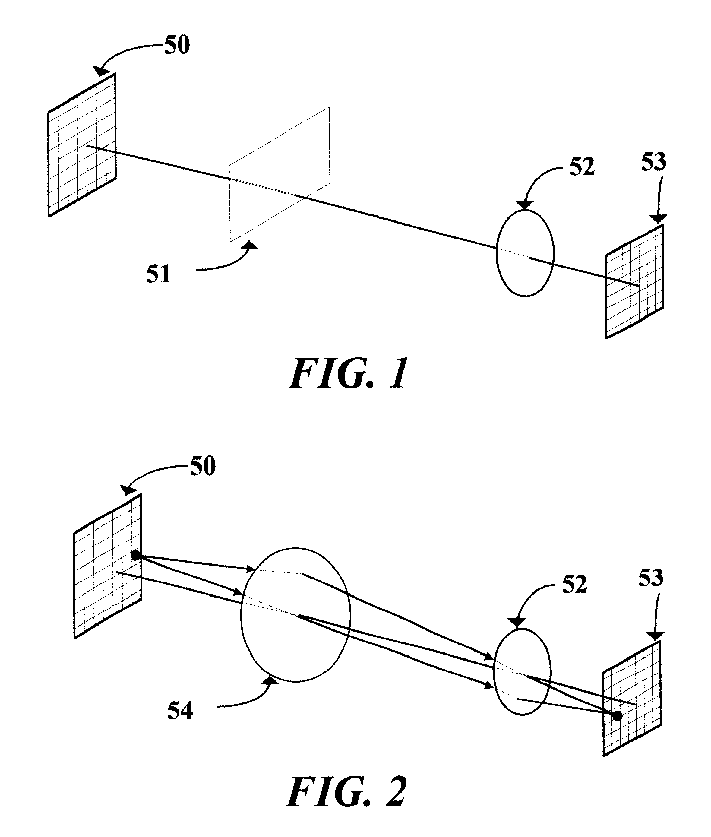
This invention relates to a novel prescription lens (58), mainly suited for ophthalmic applications. The lens designer defines the macroscopic surfaces of the lens (59, 60) as desired. The design process assumes that the location of the object (50), the lens (51), and the required image (53) are known. By using Ray-tracing technique we calculate the microscopic normals to the lens that will form the required image. From those microscopic normals we calculate microscopic surface by a process of summation the slopes with geometric pattern conditions. The final surface is not smooth but contains plenty of dense microscopic shapes that look like saw-teeth. That rough surface enables the lens to have almost any desired shape and thickness.

Description

1. Field of the InventionThis invention relates to a novel prescription lens, mainly suited for ophthalmic applications, which can be formed to almost any shape and any thickness the designer wishes to, and a method which the design is synthesized from its specification.2. Terms DefinitionThe term "eyewear" as used herein is defined as any light-transmitting element or elements in front of the eyes.The term "prescription" as used herein is defined as a specific combination of optical parameters that meets the needs of a particular person in purpose to solve a large variety of treatments and diagnostic problems known to eye specialists, or the required optical function / properties whenever the article is not an ophthalmic lens. The term "diffractive surface" as used herein is defined as an optical surface having all over the surface plurality of edges or apertures or protrusions that are designed and made in accordance with the Interference phenomena. Only whenever the exact spatial l...

Claims


Application Information

Patent Timeline
Patent Type & Authority Patents(United States)
IPC IPC(8): G02C7/02G02B3/08
CPCG02B3/08G02C7/02
Inventor GIL, THIEBERGER
Owner GIL THIEBERGER
Learn More