
Streamlined, readily towable marine seismic energy source for creating intense swept-frequency and pulse-coded signals in a body of water

a marine seismic and energy source technology, applied in seismology, seismology, instruments, etc., can solve the problems of disturbing and undesirable vibrations involving the stern portion of the vessel itself, heavy equipment, clumsy and awkward deployment behind the seagoing vessel, and affecting the seismic performance of the body of the vessel,

Inactive Publication Date: 2002-10-15
BOLT TECH CORP
View PDF2 Cites 57 Cited by
  • Summary
  • Abstract
  • Description
  • Claims
  • Application Information

AI Technical Summary

Benefits of technology

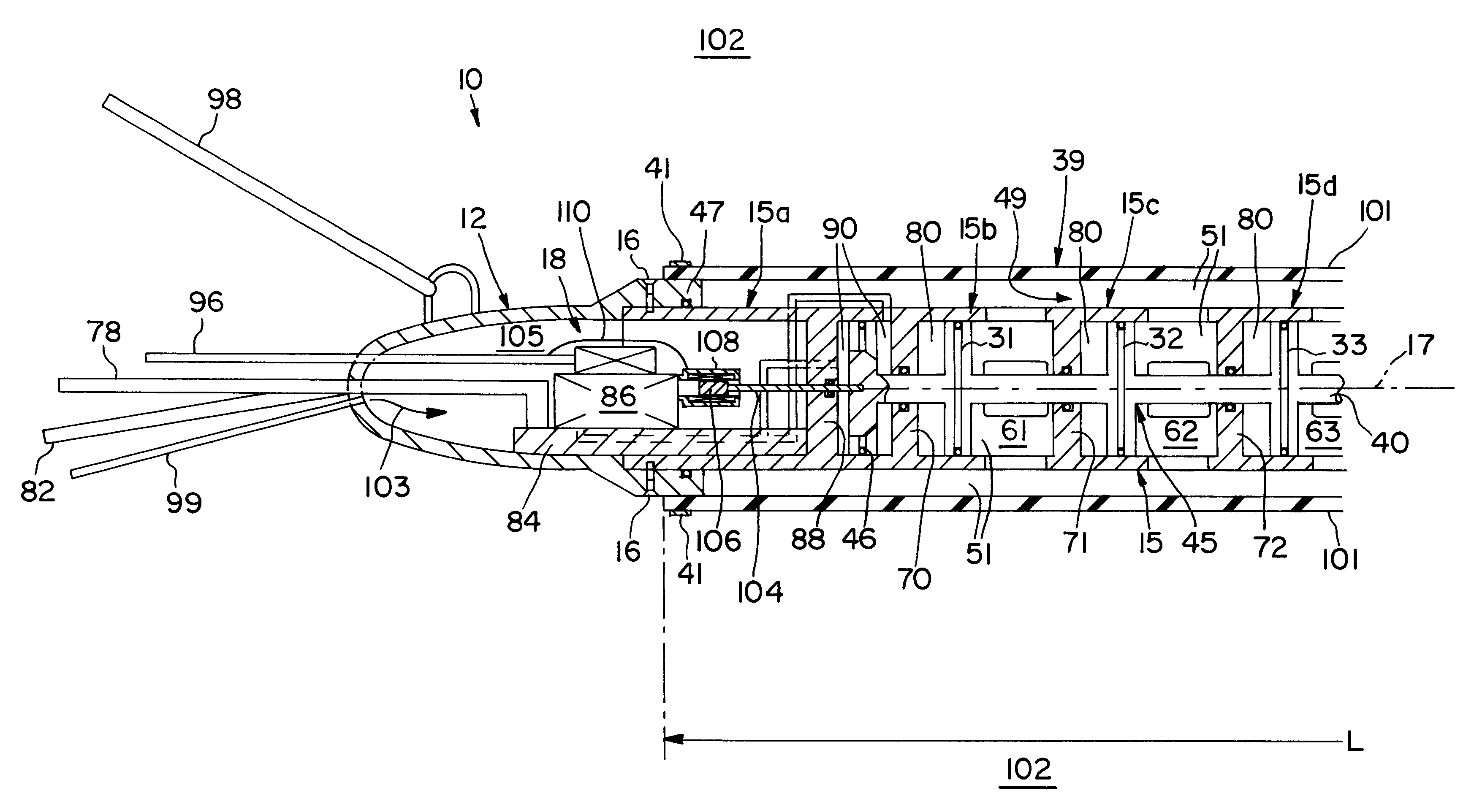
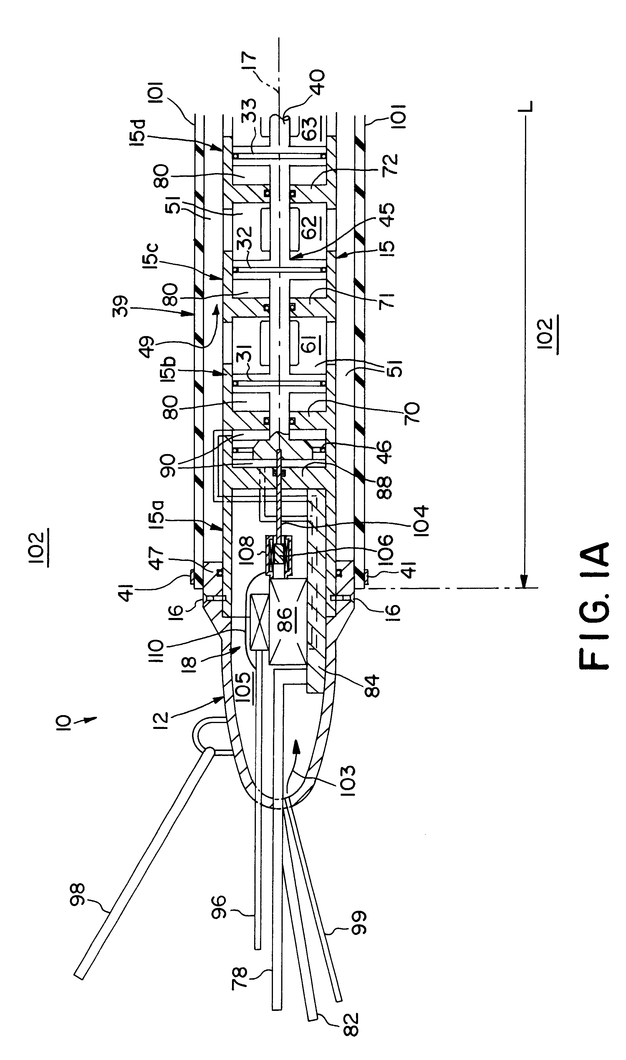
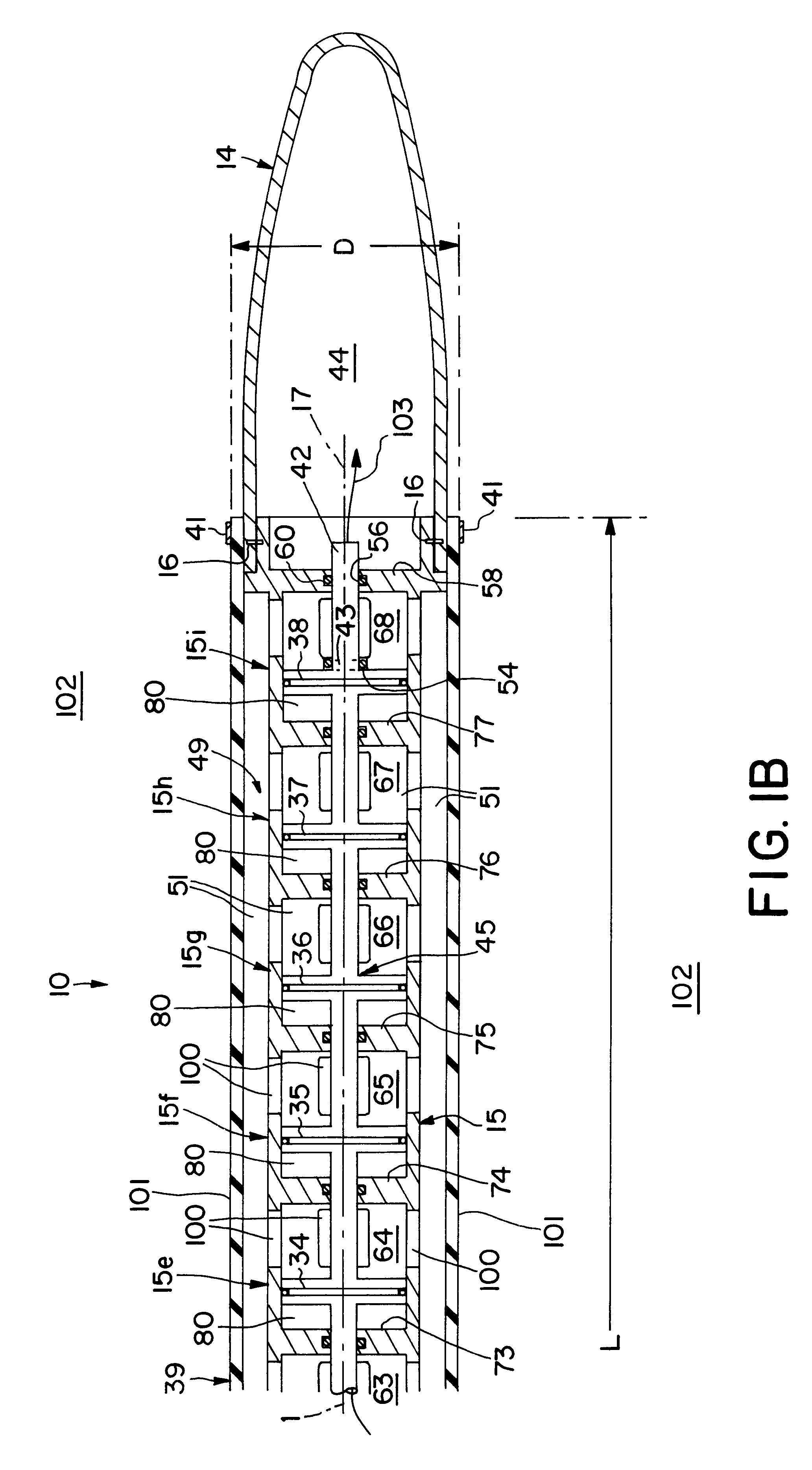
Among numerous advantages provided by the illustrative embodiment of the invention are those resulting from its dramatically large vibration-coupling surface area in contact with the body of water. Yet, this large vibrational-coupling area is achieved while also designing a low-drag configuration.
There are eight vibrator piston chambers shown. The vibrator's modular construction facilitates making such vibrators with more than eight or less than eight vibrator piston chambers, as may be beneficial for usage in various marine seismic exploration and / or surveying applications.

Problems solved by technology

There are prior vibratory-type marine seismic energy sources, but such equipment has been heavy, bulky, clumsy and awkward to deploy behind a seagoing vessel.
However, action / reaction forces generated by such stern-mounted, hydraulically-driven, vibratory, seismic energy equipment produced troublesome, disturbing and undesirable vibrations involving stern portions of the vessel itself.
Such vibrations became severe in structural members, panels, braces and the like which happened to be vibrationally resonant with fundamental and / or harmonic (overtone) frequencies generated by a large, stern-mounted, powerful, hydraulically-driven vibratory seismic energy source.
Attempts to use prior vibratory seismic energy sources separated from the vessel itself and being towed through a body of water behind the vessel have experienced considerable difficulties.
Their heavy weight and bulk have made them difficult to lift from shipboard over the stern and then lower into the water for deploying them.
They similarly were difficult to retrieve from the water to return them onto shipboard.
Furthermore, large cross-sectional areas of prior marine seismic vibratory apparatus, i.e., their frontal areas, produced unacceptably large drag forces through water, thereby tugging backward against forward motion of towing vessels.
Undesirable consequences of large drag forces are unduly large stresses in towing gear and wasteful large consumptions of fuel used in propelling towing vessels.

Method used


Image

  • Streamlined, readily towable marine seismic energy source for creating intense swept-frequency and pulse-coded signals in a body of water
  • Streamlined, readily towable marine seismic energy source for creating intense swept-frequency and pulse-coded signals in a body of water
  • Streamlined, readily towable marine seismic energy source for creating intense swept-frequency and pulse-coded signals in a body of water

Examples


Embodiment Construction

In the Drawings is shown a vibratory marine seismic energy source indicated at 10 in the four Figures comprising a preferred embodiment of the invention. This vibratory source 10 is elongated, having an overall generally circular cylindrical configuration with a streamlined nose towing head 12, and a streamlined aft tail head 14. These streamlined hollow heads 12 and 14 are suitably removably mounted on the front and aft ends of a long cylindrical tubular wall 15. This long cylinder wall 15 has a longitudinal axis 17 (FIGS. 1A and 1B) extending concentrically therein.

This long cylinder wall 15 is modular in construction comprising a plurality of cylinder sections joined in end-to-end axial alignment. For example, the source 10 as shown comprises sections 15a, 15b, 15c, 15d, 15e, 15f, 15g, 15h and 15i. Except for the front section 15a and the aft section 15i, all of the intermediate modular cylinder sections 15b to 15h are identical in construction. The front tubular section 15a is c...


PUM


Abstract

Streamlined, towable, marine seismic energy vibrator for creating intense swept-frequency and pulse-coded seismic signals in a body of water has a sleek, fish-like configuration designed for towing with minimum drag. The vibrator has a streamlined hollow towing head and a streamlined hollow tail head mounted onto front and rear of a long cylindrical tubular wall which is modular, comprising cylinder sections joined in end-to-end axial alignment. Within this long tubular cylinder wall is an axially vibratable multi-piston assembly having a plurality of pistons on a long piston rod. One piston is positioned in each of the cylinder chambers. These chambers hive multiple ports opening out through the long cylindrical wall. An elongated circular cylindrical elastomeric bladder forms a water-filled bladder chamber encircling the wall. An actuator piston is vibrated by a remotely controllably hydraulic circuit, thereby vibrating the multi-piston assembly for vibrating water out and in through multiple ports communicating with the water-filled bladder chamber for vibrating the exterior of the bladder shown having diameter "D" of 18 inches and length "L" of 118.5 inches, providing a 6,700 square inch vibration area contacting the ambient water. A multi-piston position sensor enables synchronization of the vibrator with companion sources being towed. An axial passage in the long piston rod feeds low-pressure compressed air into the cylinder chambers forming air cushions behind the pistons vibrating water in these cylinder chambers.

Description

The present invention relates to marine seismic energy sources adapted to be submerged in water aft of a seismic exploration vessel. More particularly, this invention relates to a streamlined, readily-towable marine seismic energy source for creating intense, swept-frequency and pulse-coded seismic signals in a body of water. The illustrative embodiment of the invention is a marine vibratory sound source having a sleek, fish-like configuration designed to be readily towed in the water with a minimum of drag.There are prior vibratory-type marine seismic energy sources, but such equipment has been heavy, bulky, clumsy and awkward to deploy behind a seagoing vessel.Certain prior hydraulically-actuated vibratory marine seismic energy sources were attempted to be mounted directly on the stern of a seagoing vessel. However, action / reaction forces generated by such stern-mounted, hydraulically-driven, vibratory, seismic energy equipment produced troublesome, disturbing and undesirable vibr...

Claims


Application Information

Patent Timeline
IPC IPC(8): G01V1/02G01V1/135
CPCG01V1/135
Inventor CHELMINSKI, STEPHEN
Owner BOLT TECH CORP
Learn More