Radioactive decontamination

a radioactive contamination and decontamination technology, applied in the direction of radiation therapy, electrostatic cleaning, cleaning process and apparatus, etc., can solve the problems of high running cost, ineffective decontamination techniques such as fluid shear blowing or paste/stripping, and surface contamination with radioactive substances

Inactive Publication Date: 2002-09-03
NUCLEAR DECOMMISSIONING AUTHORITY
View PDF5 Cites 6 Cited by
  • Summary
  • Abstract
  • Description
  • Claims
  • Application Information

AI Technical Summary

Problems solved by technology

During the operation of nuclear processing plants it is inevitable that surfaces will become contaminated with radioactive substances.
In such situations well known decontamination techniques such as chemical washing, fluid shear blowing or paste/stripping are not effective for the removal of embedded contamination.
However, such a scheme has a disadvantage in that running costs are

Method used


Image

  • Radioactive decontamination
  • Radioactive decontamination
  • Radioactive decontamination

Examples


Embodiment Construction

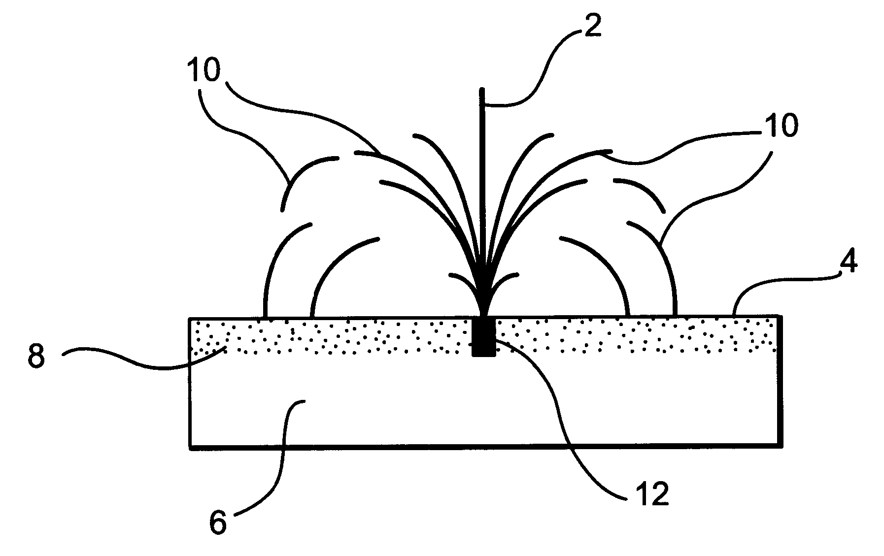
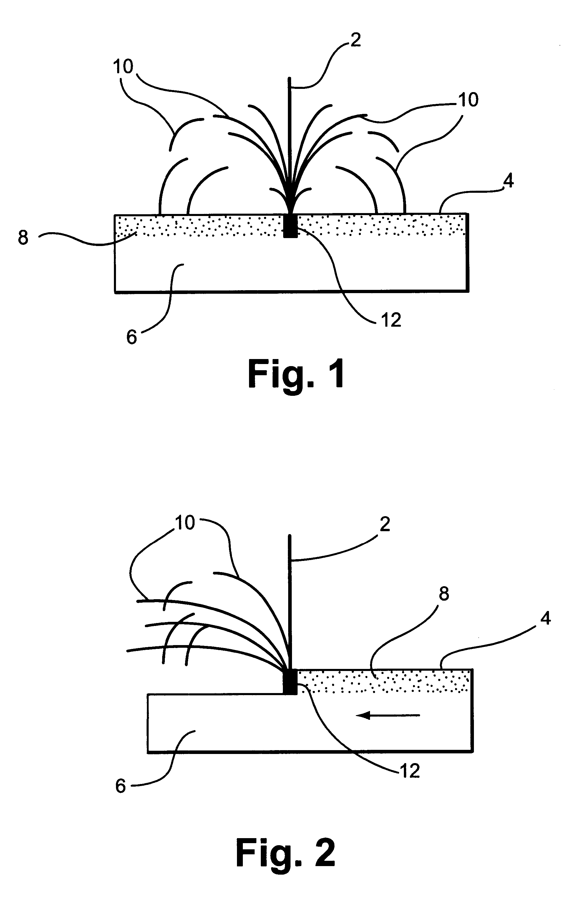
Referring now to FIG. 1, a laser beam 2 is shown impinging upon a surface 4 of a stationary metallic workpiece 6, the surface 4 having a layer of embedded radioactive contamination 8. The laser beam 2 has a power density of greater than 6 MW / cm.sup.2 and is operated at a pulse length of several milliseconds. At the point where the laser beam 2 meets the surface 4 a laser melt pool 12 is formed. Molten material 10, containing the radioactive contamination 8 is ejected from the melt pool 12 due to a laser-generated vapour recoil pressure of between 5 to 100 bar and to a lesser extent to a laser photo pressure (which is the power density divided by the speed of light). The ejected material may be thrown for distances of up to 2.5 metres from the melt pool 12.

In FIG. 2 the laser beam 2 is shown impinging upon the surface 4 of the workpiece 6 with the workpiece 6 now moving in the direction indicated by the arrow. As described in relation to FIG. 1, molten material 10 containing the radi...


PUM

PropertyMeasurementUnit
Pressureaaaaaaaaaa
Timeaaaaaaaaaa
Metallic bondaaaaaaaaaa

Abstract

A method for the removal of embedded contamination from a metallic surface in which a laser beam is directed on to the contaminated surface. The laser beam has sufficient power density to cause direct ejection of laser-generated melt pool liquid from the metallic surface thereby removing a metallic surface layer containing the embedded contamination. Means are provided for the collection of laser ejected material in order to prevent recontamination of the metallic surface or contamination of previously uncontaminated surfaces.

Description

This application is a 371 of PCT / G02452 filed Nov. 8, 1994.1. Field of the InventionThis invention relates to the removal of radioactive contamination and, more particularly, to the removal of embedded radioactive contamination from metallic surfaces using laser beams.2. Discussion of Prior ArtDuring the operation of nuclear processing plants it is inevitable that surfaces will become contaminated with radioactive substances. Consequently, during the decommissioning of these plants it is necessary to decontaminate the contaminated surfaces in a safe manner. Often the contaminated surfaces comprise stainless steels or mild steels and typical contaminants include UO.sub.2, PuO.sub.2, Co-60, Sr-90, Cs-134 and Cs-137. The contaminants may be in the form of fine particles or solutions which can penetrate into steel substrates for a distance of about 4 mm. In such situations well known decontamination techniques such as chemical washing, fluid shear blowing or paste / stripping are not effe...

Claims


Application Information

Patent Timeline
IPC IPC(8): B08B7/00G21F9/00G21F9/28
CPCB08B7/0042G21F9/005
Inventor LI, LINSTEEN, WILLIAM MMODERN, PETER J
Owner NUCLEAR DECOMMISSIONING AUTHORITY
Why Eureka
Try Eureka