
Process and device for spraying a moving fibrous web

a technology of moving fibrous web and process, which is applied in the field of process for spraying a moving fibrous web, can solve the problems of large space demand, large cost of valve block, and stepped volume flow characteristic that can be created

Inactive Publication Date: 2002-09-03
VOITH PATENT GMBH
View PDF15 Cites 13 Cited by
  • Summary
  • Abstract
  • Description
  • Claims
  • Application Information

AI Technical Summary

Benefits of technology

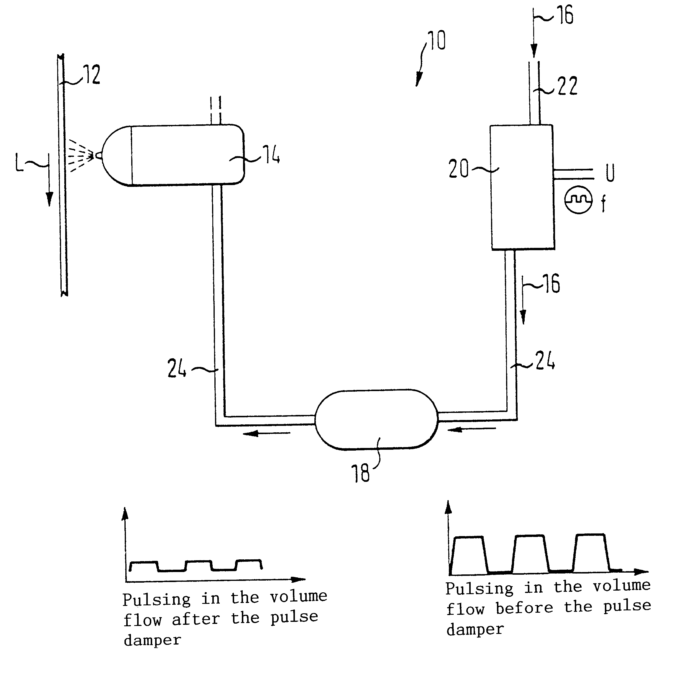
Pulsing dampers or impulse dampers use the compressibility of gases to level pressure variations. The arrangement of the inlet line and the outlet line in a substantially larger closed gas volume, compared with the pipe diameter, enables the influx of the liquid until both cross-sections (inlet and outlet) are submerged in the liquid. The remaining gas volume is enclosed and is therefore compressed in accordance with the applied pressure. The pre-filling pressure of the gas is adjusted to the operating pressure. Rapidly occurring pressure changes (pulses) change the volume of the enclosed gases (mostly air). The energy transforming compression and expansion of the gas buffer smooths the occurring pulses.
The present invention is directed to a process for spraying a moving fibrous web with at least one jet. The process includes feeding a controlled volume flow of a spray agent to the at least one jet through at least one pulsing valve, and damping and reducing pulses occurring in the controlled volume flow of the spray agent.

Problems solved by technology

This control concept has the disadvantage that only a stepped volume flow characteristic can be created by addition.
Another disadvantage is the large number of separate valves per jet and the resulting large demand for space, and the large expense of the valve block.
This control concept has the disadvantage that only a stepped volume flow characteristic can be created by addition.
Another disadvantage is the large number of separate valves per jet and the resulting large expense of the combined spray unit.
At the present state of the art, proportional valves are rarely used in small volume flows since the control range is too narrow and the danger of clogging is too great.
Additionally, these valves are very expensive.

Method used


Image

  • Process and device for spraying a moving fibrous web
  • Process and device for spraying a moving fibrous web
  • Process and device for spraying a moving fibrous web

Examples


Embodiment Construction

The particulars shown herein are by way of example and for purposes of illustrative discussion of the embodiments of the present invention only and are presented in the cause of providing what is believed to be the most useful and readily understood description of the principles and conceptual aspects of the present invention. In this regard, no attempt is made to show structural details of the present invention in more detail than is necessary for the fundamental understanding of the present invention, the description taken with the drawings making apparent to those skilled in the art how the several forms of the present invention may be embodied in practice.

FIG. 1 depicts a schematic partial representation of a possible embodiment of a device 10 for spraying a moving fibrous web 12. The fibrous web 12 can be, in particular, a paper or a cardboard web. The device 10 includes at least one jet 14 that is supplied with a preferably controlled volume flow of the relevant spray agent 16...


PUM

PropertyMeasurementUnit
Lengthaaaaaaaaaa
Lengthaaaaaaaaaa
Fractionaaaaaaaaaa

Abstract

Process and apparatus for spraying a moving fibrous web with at least one jet. The process includes feeding a controlled volume flow of a spray agent to the at least one jet through at least one pulsing valve, and damping and reducing pulses occurring in the controlled volume flow of the spray agent. The apparatus includes at least one jet arranged to be fed with a controlled volume flow of a spray agent, at least one pulsing valve which feeds the controlled volume flow of the spray agent to said at least one jet, and at least one pulse damper arranged to damp or reduce pulses occurring in the controlled volume flow of the spray agent.

Description

1. Field of the InventionThe invention relates to a process for spraying a moving fibrous web, in particular a paper or a cardboard web, by at least one jet, in which a preferably controlled volume flow of the corresponding spray is fed to the jet. It further relates to a device for spraying a moving fibrous web, in particular, a paper or cardboard web with at least one jet, to which a preferably controlled volume flow of the corresponding spray agent can be fed.2. Discussion of Background InformationSpray arrangements are used in the production, refinement, and processing of fibrous webs in order to purposefully influence certain web characteristics. These characteristics can be, for instance, the moisture content, the surface moisture, the surface coating, and / or the like. Alternately or additionally the inoculation of additional materials is possible.At present the following two general concepts are used in applications in which a variable volume flow is sprayed (compare, e.g., t...

Claims


Application Information

Patent Timeline
IPC IPC(8): B05B9/03B05B1/30D21G7/00D21H23/00D21H23/50B05B1/02B05B1/08B05B12/06
CPCB05B1/30B05B9/03D21G7/00D21H23/50B05B1/08
Inventor WOLF, ROBERTOECHSLE, MARKUSWEGEHAUPT, FRANKBENDIG, LOTHARLANDVATTER, KLAUSGAA, REINHARD
Owner VOITH PATENT GMBH
Learn More