
Data storage to enhance timing recovery in high density magnetic recording

a high density magnetic and data storage technology, applied in the field of timing, can solve the problems of reducing the efficiency of data storage, affecting the timing recovery of high density magnetic recordings, and unable to meet the requirements of the application,

Inactive Publication Date: 2002-08-06
LINKEDIN
View PDF13 Cites 17 Cited by
  • Summary
  • Abstract
  • Description
  • Claims
  • Application Information

AI Technical Summary

Benefits of technology

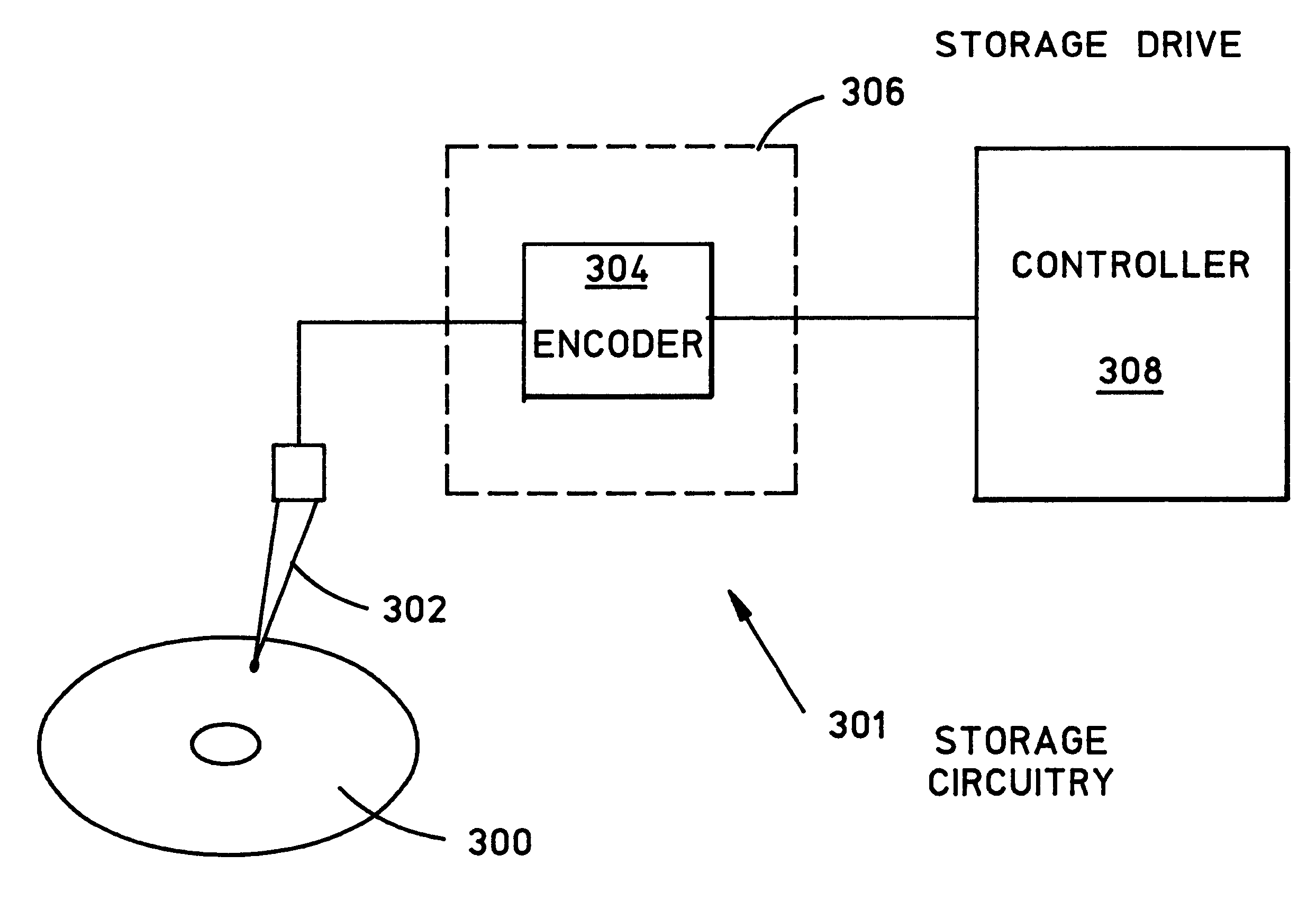
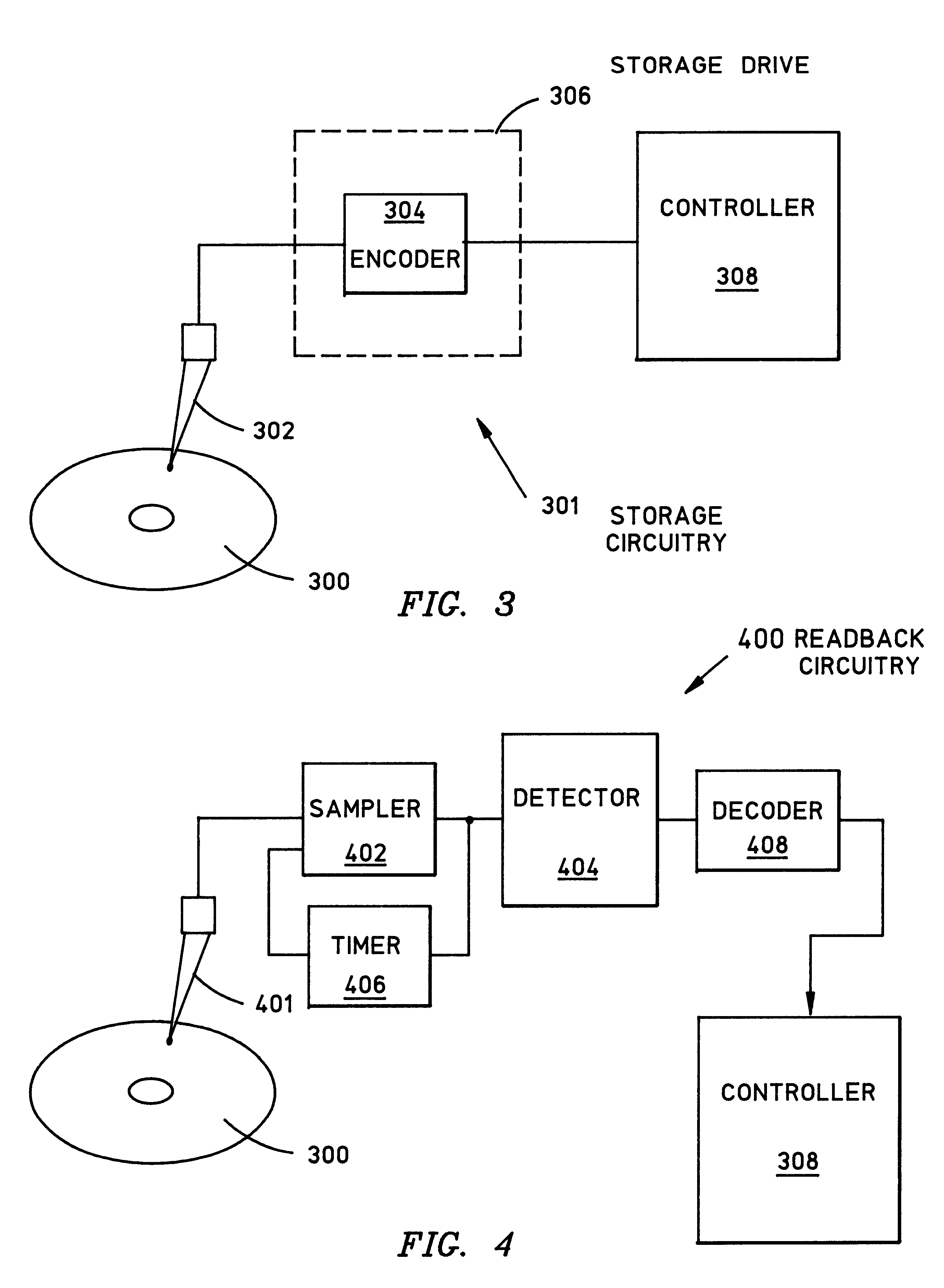
In one embodiment, the present invention concerns a method for encoding a binary sequence of user data for storage on a magnetic data storage medium such as a disk or tape. First, the input sequence to be stored is received in the form of a binary sequence. Then, the uncoded binary sequence is encoded to enable the timing of subsequent readback operations. More particularly, the uncoded binary sequence is encoded such that the encoded binary sequence contains a specific binary pattern, occurring with at least a guaranteed minimum level of frequency. This allows precise timing during readback, as discussed below. To facilitate storage efficiency, the binary pattern may be relatively short, such as "010".

Problems solved by technology

Therefore, this approach may not be completely satisfactory in applications where storage space is limited or expensive.
It may also be a more lengthy sequence, such as "00100" and "11011", respectively, although this reduces the data storage efficiency.
Unless the samples of the continuous analog readback waveforms are evaluated properly, the analog "peaks" can be difficult to identify.
In the case where timing "peaks" are used (e.g., corresponding to "010" bit patterns), the two consecutive samples are not useful in evaluating and correcting timing unless the samples have like mathematical signs.

Method used


Image

  • Data storage to enhance timing recovery in high density magnetic recording
  • Data storage to enhance timing recovery in high density magnetic recording
  • Data storage to enhance timing recovery in high density magnetic recording

Examples


Embodiment Construction

While there have been shown what are presently considered to be preferred embodiments of the invention, it will be apparent to those skilled in the art that various changes and modifications can be made herein without departing from the scope of the invention as defined by the appended claims.

For example, the threshold may be changes to obtain a greater or lesser timing adjustment sensitivity.

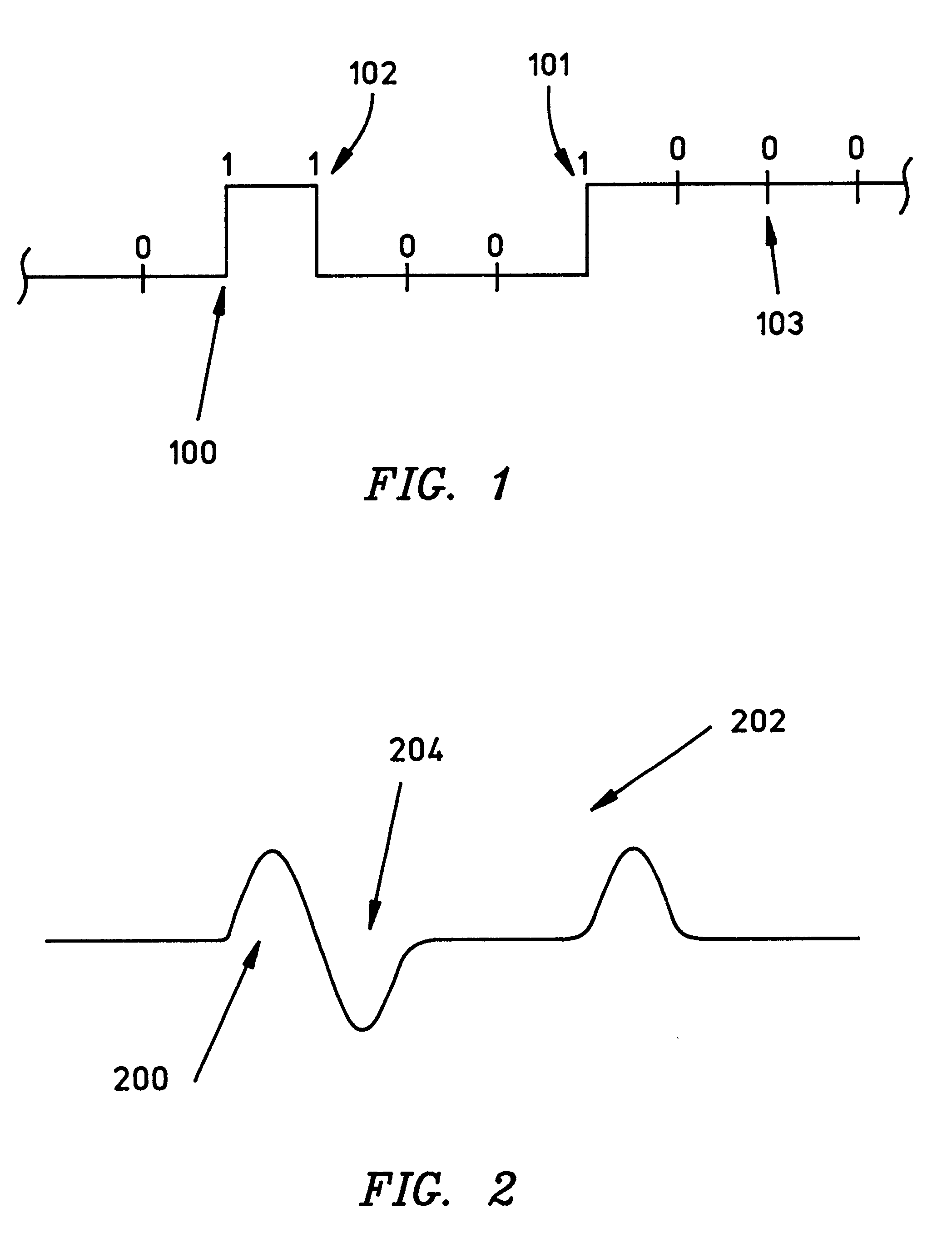
Additionally, instead of basing timing adjustments upon "peaks" (as shown above), timing adjustment may be performed using zero-crossings. As mentioned above, zero-crossings are features in the analog readback waveform produced in response to binary bit patterns such as "101". When zero-crossings are used instead of peaks, the operation of tasks 1200 of FIG. 12 differ from that described above in a number of respects. First, query 1206 only concludes that timing adjustment is possible if the two consecutive samples have opposite signs. Another difference occurs in the operation of queries 1210 ...


PUM

PropertyMeasurementUnit
magnetic flux transitionsaaaaaaaaaa
frequencyaaaaaaaaaa
degree of frequencyaaaaaaaaaa

Abstract

A timing recovery system encodes data while impressing recognizable patterns thereon, enabling precise timing during subsequent readback operations. An uncoded binary sequence is encoded using an m / n rate block coded sequence, incorporating a unique predetermined binary bit pattern that occurs with a selected level of frequency. The encoded sequence is stored on the recording medium as a series of flux transitions. To read back the stored data, a read head measures the flux transitions stored on the medium and generates a representative analog waveform. A sampler samples the waveform in accordance with a timing scheme provided by a timing circuit. The timing circuit adjusts the timing of the samples to ensure that the analog waveform is sampled at appropriate times to yield the most accurate results. The timing circuit evaluates two consecutive samples to identify samples associated with features of the analog readback waveform that corresponds to the predetermined bit patterns. Identified samples are then compared to determine whether timing of samples should be advanced, retarded, or retained with respect to the analog waveform. After a detector translates samples into an enclosed binary bit stream, a decoder decodes the detector's binary bit stream by revising the original encoding process, recreating the original encoded binary sequence.

Description

1. Field of the InventionThe present invention relates to the timing of operations conducted to read digital data that is stored on recording media such as magnetic tape or disk media. More particularly, the invention concerns a system for encoding binary user data and imposing frequent recognizable bit patterns thereon to serve as self-clocking events during subsequent readback. The invention also concerns a system for performing timing recovery on readback of encoded waveforms.2. Description of the Related ArtTo store user data on a magnetic data storage medium, a data drive writes positive and negative "flux transitions" to the medium. Under the "NRZI" protocol (FIG. 1), a binary "one" may be stored by writing either a positive flux transition (e.g., 100 or 101), or a negative flux transition (e.g., 102) to the medium. A binary "zero" is represented by the absence of a flux transition (e.g., 103). Each binary bit (whether a "one" or a "zero") is written to the storage medium acco...

Claims


Application Information

Patent Timeline
Patent Type & Authority Patents(United States)
IPC IPC(8): G11B20/14G11B5/09
CPCG11B5/09G11B20/1426
Inventor BLAUM, MARIOMELAS, CONSTANTIN MICHAEL
Owner LINKEDIN
Learn More