
Powder injector for ladle

a technology of injector and ladle, which is applied in the direction of manufacturing converters, furnaces, charge manipulation, etc., can solve the problem of violent reaction in the body of molten metal

Inactive Publication Date: 2002-06-25
MAGNESIUM TECH CORP
View PDF5 Cites 8 Cited by
  • Summary
  • Abstract
  • Description
  • Claims
  • Application Information

AI Technical Summary

Benefits of technology

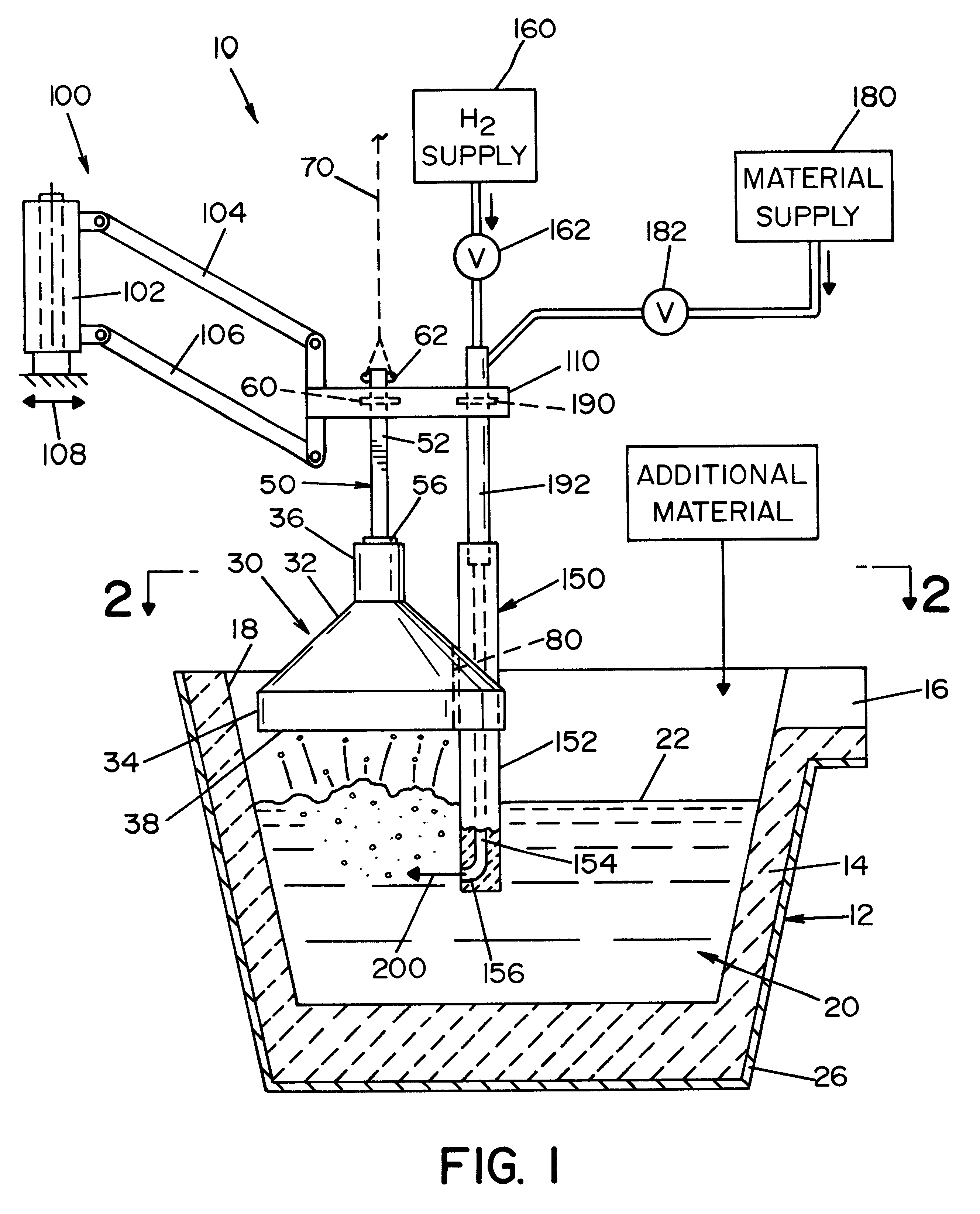
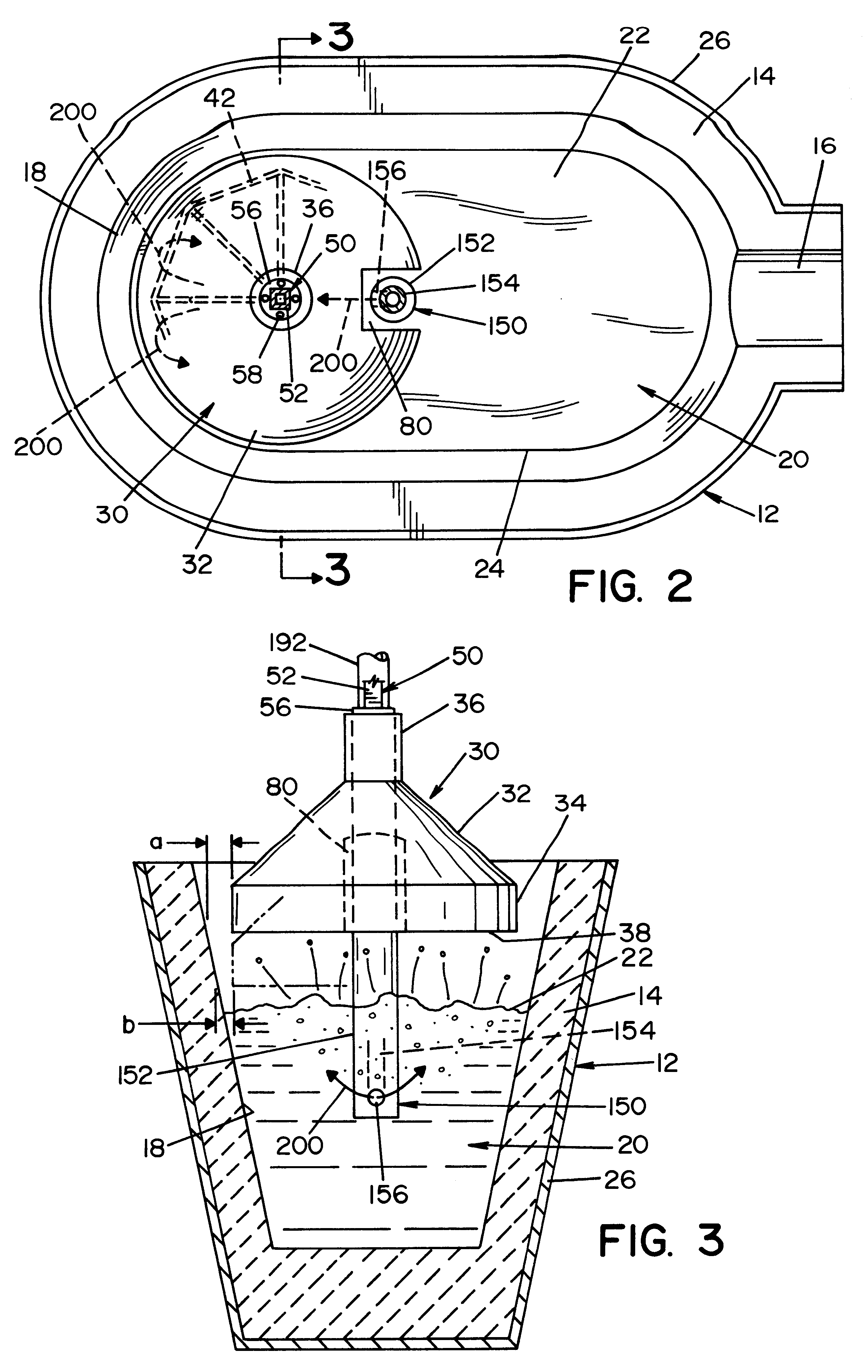
The present invention relates to a powder injector for a small ladle of molten metal having an exposed upper surface. This powder injector allows powder carried by a gaseous media, preferably nitrogen, through a lance to be injected under the surface of the molten metal, without the problems experienced by splashing and spraying of molten metal from the ladle during the powder injection process. This new powder injector comprises a splash deflector with a cast body of heat resistant material. A downwardly facing lower surface of the body defining an outer periphery is suspended over the upper level of molten metal, whereby the downwardly facing surface is just above the molten metal. The outer periphery of the splashing deflector cast body has a notch to accommodate an elongated powder injection lance with a tubular body extending vertically from above the deflector surface to a position substantially below the molten metal surface and into the molten metal. This lance includes a directional outlet nozzle for directing the powder in a path at a transverse angle to the lance body. The powder and gaseous carrier is maintained below the large lower surface of the deflector body. By suspending both the lance and the splash deflector from a common mechanism, the powder injector can be lowered into the ladle. The periphery may be contoured to match this one side in one embodiment; however, this is not a requirement. The injector can be positioned away from the side or adjacent an opposite side. The downward movement of the deflector and lance is stopped when the surface of the cast body is slightly above the molten metal surface and the lance is below the surface. The lance nozzle directs powder and the gaseous carrier in a path generally bisecting the deflector lower surface, whereby all agitation of the molten metal occurs below the surface of the deflector.
In accordance with another aspect of the present invention, there is provided a method of injecting powder into a molten metal in a ladle, wherein the molten metal has an upper level with an exposed large shape. Powder is injected into the molten metal by a lance having a position below the upper surface of the metal and injected under the deflector. The powder injection path is covered by placing the splash deflector over the upper level of metal. A lower large surface is above the powder injection path. Consequently, the injected powder and gas carrier cause violent reaction in the body of the molten metal below the surface of the splash deflector and near the injector. The remainder of the molten metal remains quiescent and can be charged with other constituents, if desired. There is no need to remove the splash deflector for injecting of powder into the molten metal.
Still a further object of the present invention is the provision of a method of injecting powder into a molten metal, which method prevents unwanted splashing and loss of the powdered material.

Problems solved by technology

Consequently, the injected powder and gas carrier cause violent reaction in the body of the molten metal below the surface of the splash deflector and near the injector.

Method used


Image

  • Powder injector for ladle
  • Powder injector for ladle
  • Powder injector for ladle

Examples


Embodiment Construction

Referring now to the drawings, wherein the showings are for the purpose of illustrating the preferred embodiment of the invention only and not for the purpose of limiting same, FIGS. 1-3 show a powder injector 10 for injecting powder, such as magnesium, into a ladle 12 of a foundry or ferro alloy plant. Ladle 12 has a ceramic or refractory liner 14, a pouring spout 16 and one side area 18 at the left of the ladle as shown in FIGS. 1 and 2. Molten metal 20 in the preferred embodiment is ferro silicon and has an upper level 22 with an oblong shape 24, as shown in FIG. 2. Outer support casing 16 holds ladle 12 in position with respect to an appropriate heating mechanism (not shown) to heat or maintain the molten condition of metal 20. Power injector 10 includes splash deflector 30 having a cast heat resistant body 32 in the form of an inverted cone with a cylindrical skirt 34 and an upper cylindrical neck 36. Body 32 is cast from a heat resistant ceramic material to define lower, downw...


PUM

PropertyMeasurementUnit
Electrical resistanceaaaaaaaaaa
Shapeaaaaaaaaaa
Radiusaaaaaaaaaa

Abstract

A powder injector for a ladle of molten metal having an exposed upper level with a given shape. The injector comprises a splash deflector with a cast body of heat resistant material with a downwardly facing lower surface defining an outer periphery and maintained above the upper level of molten metal, an elongated powder injection lance with a tubular body extending vertically from above the deflector surface to a position substantially below the surface and into the molten metal and a directional outlet nozzle directed at a transverse angle to the lance body in a direction below the surface of the splash deflector and an upper member mounting the lance with respect to the splash deflector with the nozzle directed into the molten metal substantially below the lower surface and within the periphery of the lower surface.

Description

The present invention relates to the alloying of molten metal and more particularly to the concept of a powder injector for small ladles of the type used in alloying molten metal.INCORPORATION BY REFERENCEThe invention relates to ladles of the type used in foundries or ferro alloying plants, such as generally illustrated in Fadler U.S. Pat. No. 3,486,745. In the past, molten metal is alloy in relatively small ladles, such as a ladle having a capacity of less than about 10 tons. These ladles are heated by external sources, such as electrical induction or gas heating, and, to prevent splashing, a removable lid or cover is employed. Such ladle is illustrated in Fadler U.S. Pat. No. 3,486,745 that is incorporated by reference as background information.BACKGROUND OF INVENTIONProduction of alloys such as ferro silicon magnesium involves the melting of ferro silicon in a relatively small ladle. To introduce the desired amount of magnesium, a large bar or ingot of manganese is lowered into ...

Claims


Application Information

Patent Timeline
IPC IPC(8): C21C7/00F27D3/00F27D3/18F27D23/00F27D99/00
CPCC21C7/0037F27D3/18F27D2099/0095
Inventor LAWSON, PAUL D.
Owner MAGNESIUM TECH CORP
Learn More