Planar blind-mate connectors
- Summary
- Abstract
- Description
- Claims
- Application Information
AI Technical Summary
Benefits of technology
Problems solved by technology
Method used
Image
Examples
Embodiment Construction
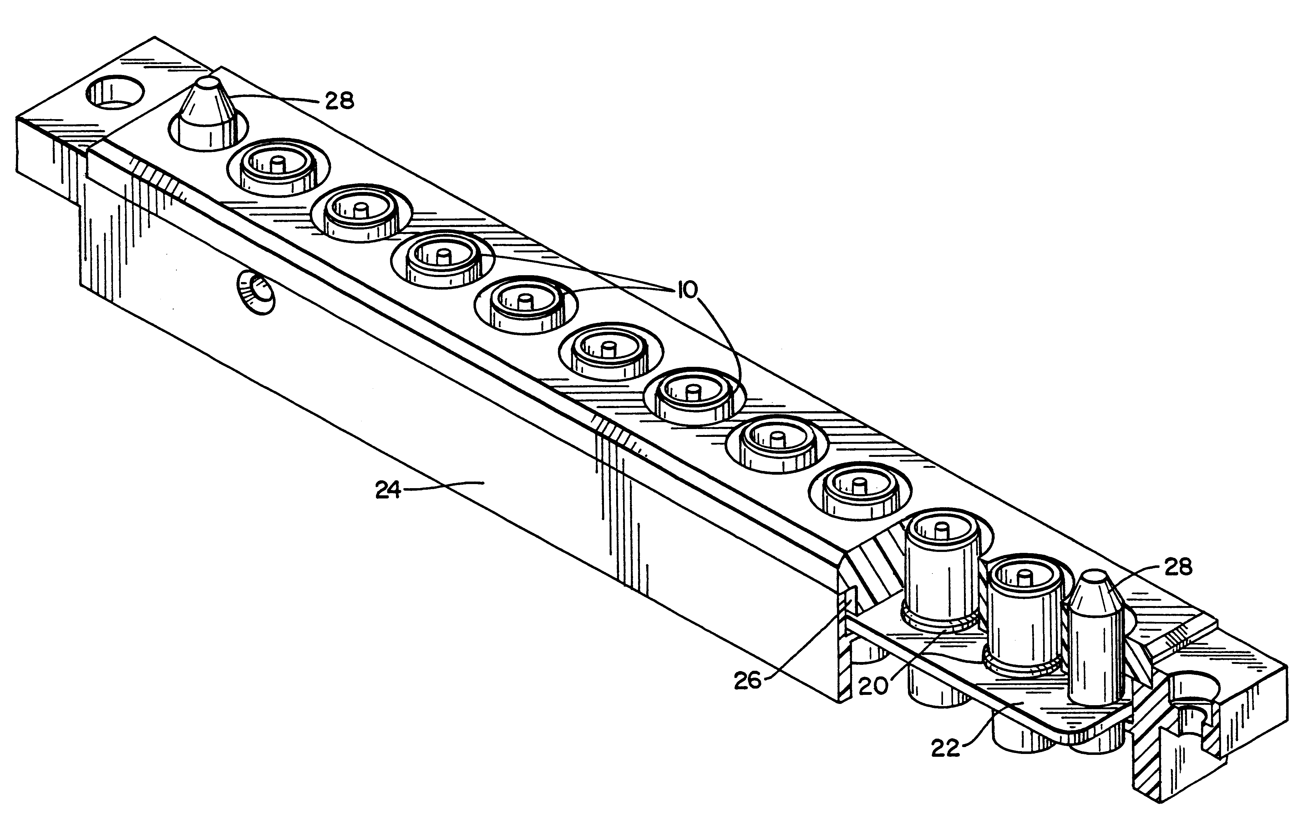
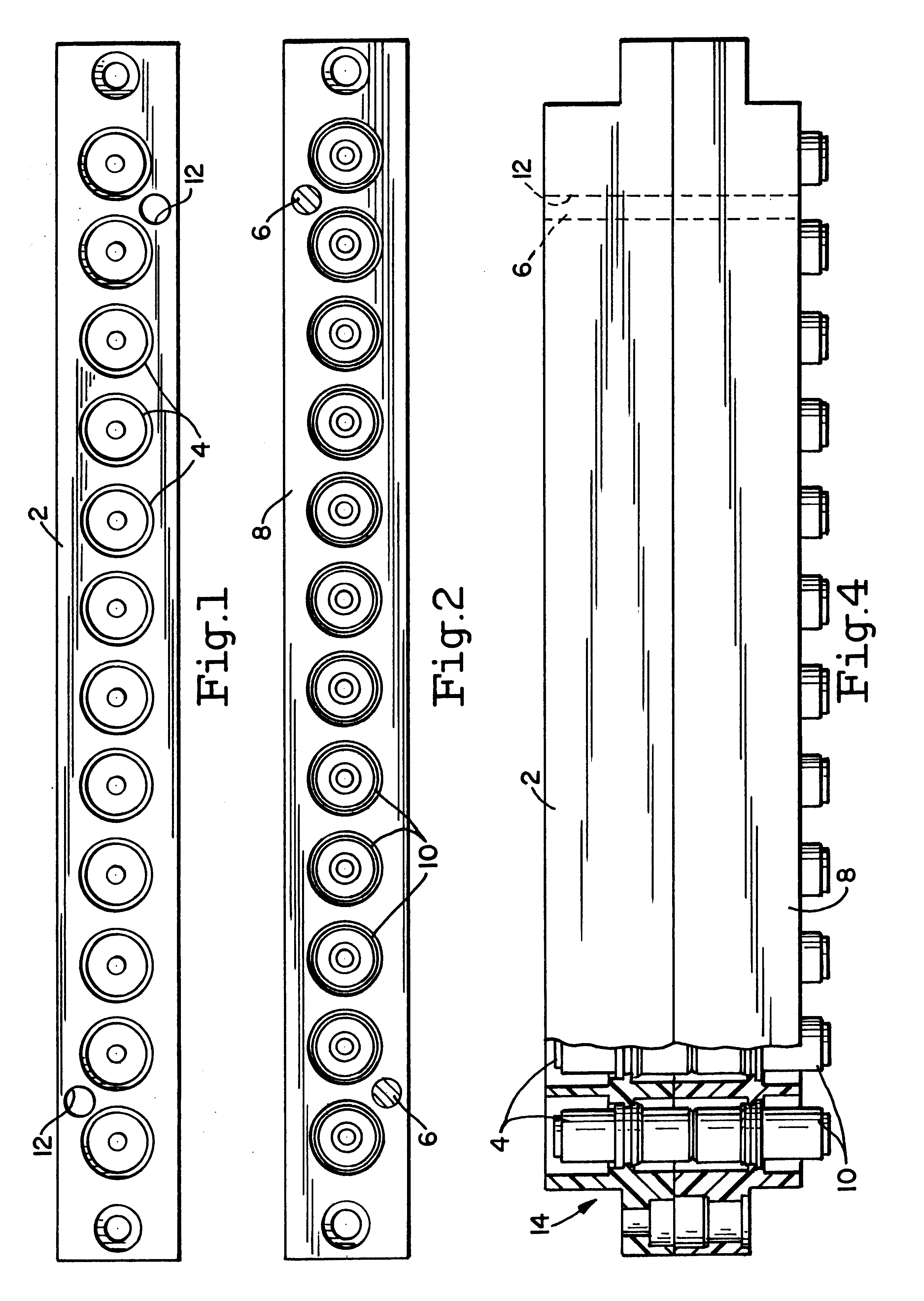
Referring now specifically to FIG. 1 of the accompanying drawings, a module 2 has mounted therein twelve fixed planar blind-mate connectors 4 and has in the surface two alignment holes 12 located, for instance, between the two end contacts at each end of the frame. Although illustrated as having twelve members, five, ten and twelve member arrays are quite common, as are others.
A module 8 carries the corresponding floating connectors 10 for mating with the fixed planar connectors in the other frame, FIG. 1. Mating of the connectors of FIGS. 1 and 2 is illustrated in FIG. 4. In this FIG. 4, floating connectors 10 of FIG. 2 are intended to mate with connectors 4 of FIG. 1. The module 8 of FIG. 2 has alignment pins 6 for mating with alignment holes 12 of module 2. The alignment pins insure proper mating of the connectors of the two modules. The various structures of the floating connectors are discussed below.
Referring now to FIGS. 3, 5 and 6, there are illustrated one arrangement of se...
PUM
 Abstract
Description
Claims
Application Information
 - R&D
- Intellectual Property
- Life Sciences
- Materials
- Tech Scout
- Unparalleled Data Quality
- Higher Quality Content
- 60% Fewer Hallucinations
Browse by: Latest US Patents, China's latest patents, Technical Efficacy Thesaurus, Application Domain, Technology Topic, Popular Technical Reports.
© 2025 PatSnap. All rights reserved.Legal|Privacy policy|Modern Slavery Act Transparency Statement|Sitemap|About US| Contact US: help@patsnap.com


