
Switch

a technology of switches and switches, applied in the direction of contacts, snap-action arrangements, contact vibration/shock damping, etc., can solve the problems of short contact life and false operation, and achieve the effect of high productivity

Active Publication Date: 2014-02-25
ORMON CORP
View PDF5 Cites 2 Cited by
  • Summary
  • Abstract
  • Description
  • Claims
  • Application Information

AI Technical Summary

Benefits of technology

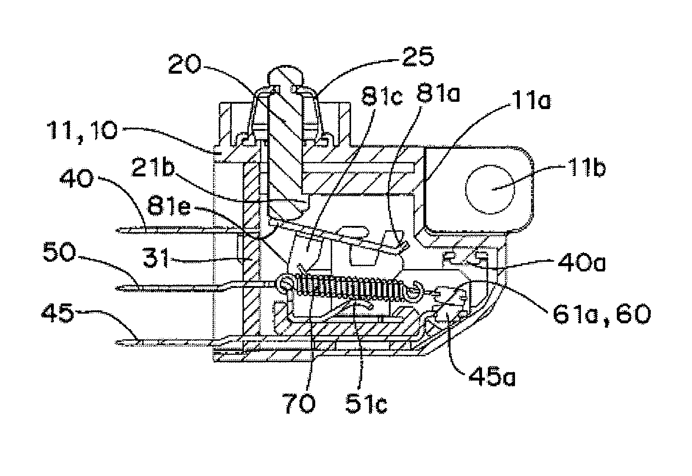
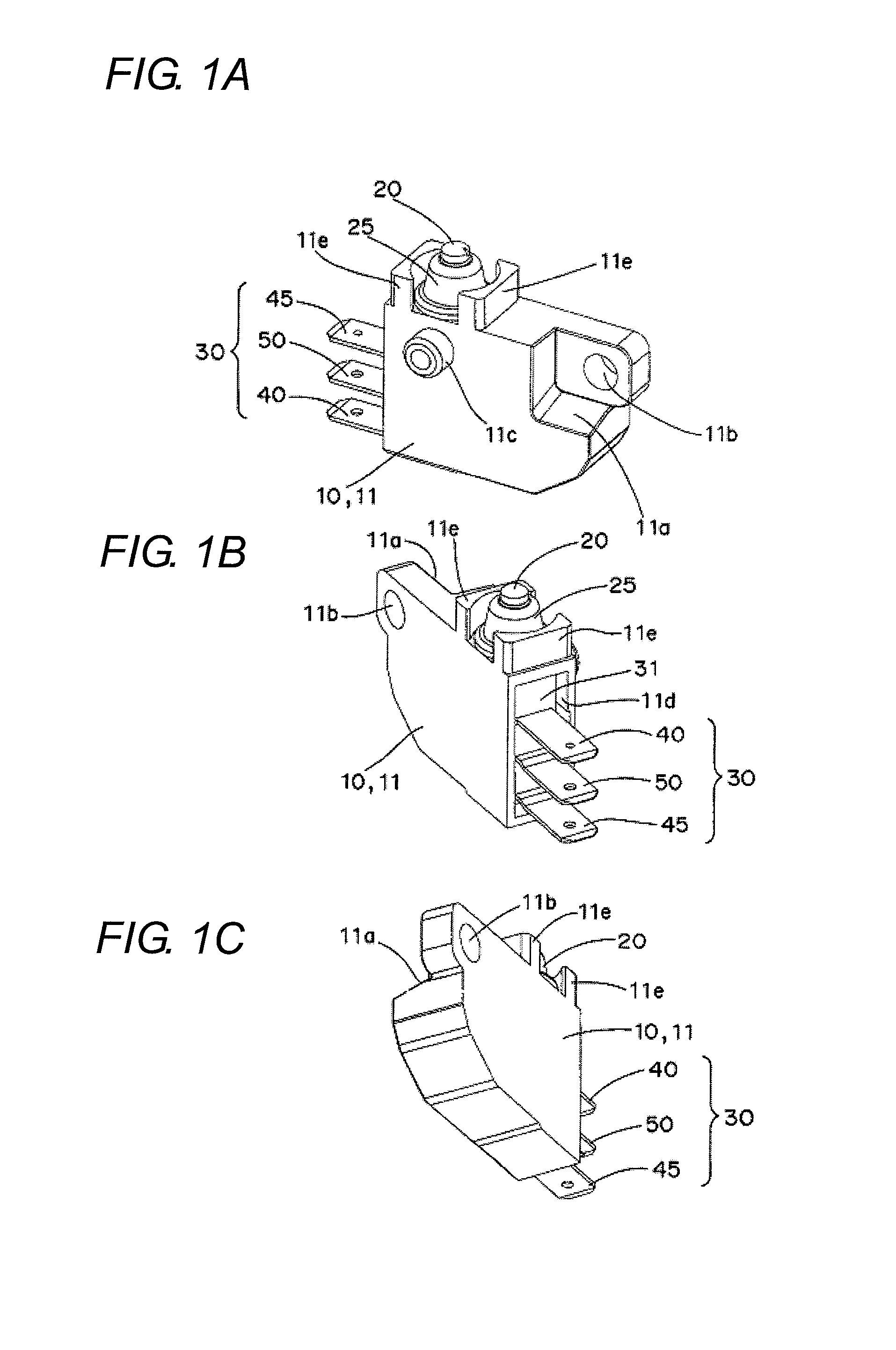
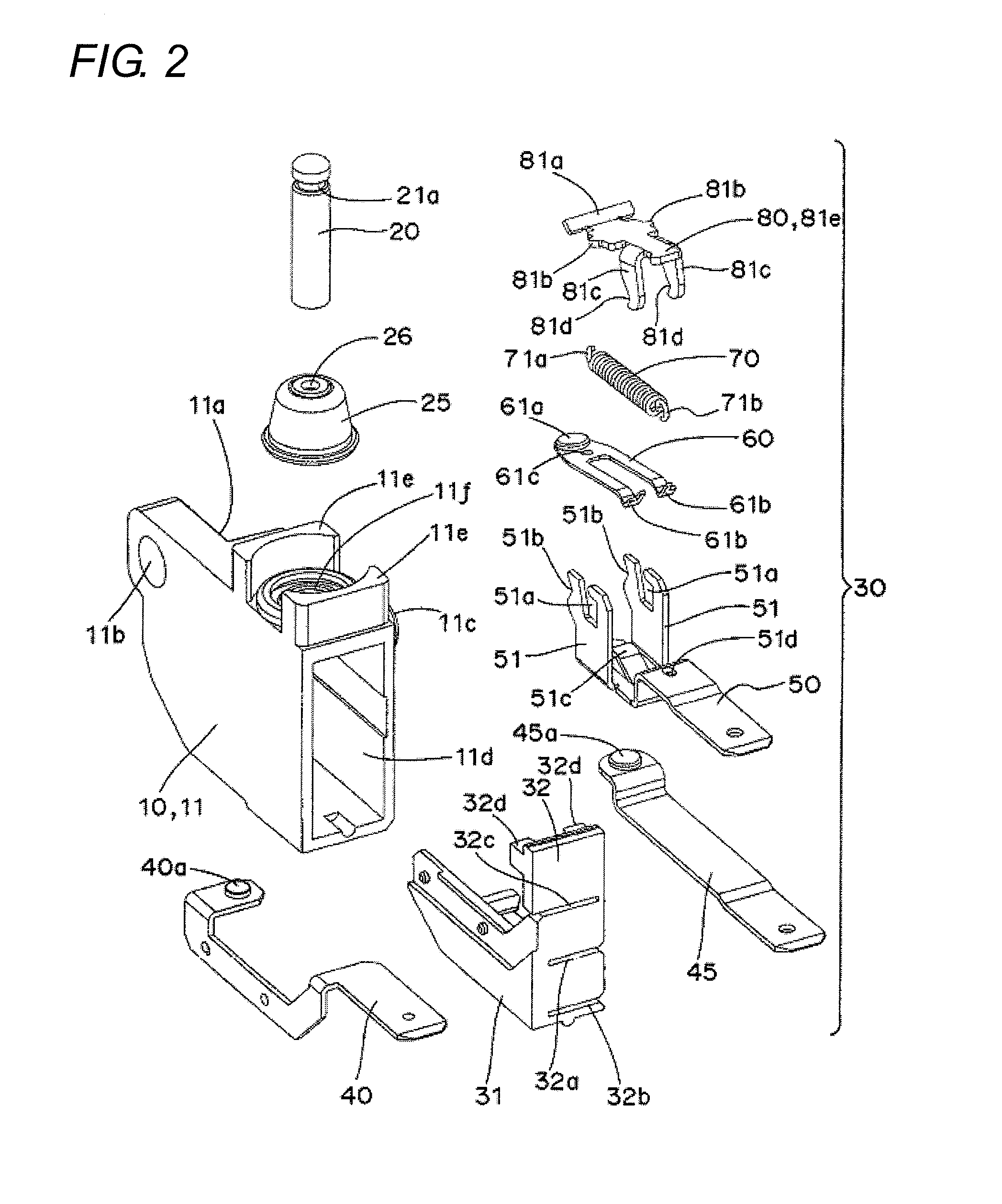
[0006]One or more embodiments of the present invention provides a switch capable of inhibiting the occurrence of the resonance phenomenon caused by the increase of the amplitude of the spring member and preventing false operation, and furthermore, preventing the breakage of the spring member and realizing long contact lifespan.
[0008]According to one or more embodiments of the present invention, when the contact mechanism is operated with the operating element or when the impact force is applied from the outside, the spring member is not brought into contact with the regulating means if the spring member is not vibrating, whereas the spring member is brought into contact with the regulating means if the spring member is vibrating, particularly, if the spring member starts to vibrate. As a result, the regulating means shifts the timing to increase the amplitude of the spring member so that the amplitude of the spring member does not increase and the resonance phenomenon can be inhibited. Therefore, the false operation can be prevented, and furthermore, the breakage of the spring member can be prevented and the wear of the contact can be reduced so that a switch of longer contact lifespan can be realized.
[0012]Accordingly, a switch with less number of components and number of assembly steps and with high productivity can be obtained.
[0016]Accordingly, a switch with less number of components and number of assembly steps and with high productivity can be obtained.
[0018]Accordingly, a switch with high productivity can be obtained by integrally molding the regulating means at the same time as the housing.

Problems solved by technology

When the resonance phenomenon occurs, not only does false operation occur, but the spring member easily breaks, the contact wears, and the contact lifespan becomes short.

Method used


Image

  • Switch
  • Switch
  • Switch

Examples


example

[0120]The resonance experiment was conducted using samples of the switches according to the first and second embodiments as an example. The resonance experiment was similarly conducted under the same condition using a sample of a switch in which the tongue piece is not arranged as a comparative example. The measurement results are shown in the graph of FIG. 33.

[0121]As shown in FIG. 33A, the resonance phenomenon did not occur in the coil spring in the example in which the tongue piece is arranged.

[0122]As apparent from FIG. 33B, the coil spring greatly vibrates and resonates in the comparative example in which the tongue piece is not arranged. Thus, it tends to easily break with increase in the number of stress oscillations and the lifespan also becomes shorter even if the stress amplitude width is within the elastic region. It is also recognized that the movable contact piece and the movable contact also vibrate with the resonance phenomenon of the coil spring.

[0123]According to th...


PUM


Abstract

A switch has a housing, a contact mechanism having a movable contact piece disposed in the housing, an operating element that operates the movable contact piece, a spring member of the contact mechanism that operates the movable contact piece to open and close a contact, and a regulating mechanism that suppresses vibration of the spring member arranged at a position contacting the spring member.

Description

BACKGROUND OF THE INVENTION[0001]1. Technical Field[0002]The present invention relates to switches, and in particular, to a micro-switch capable of inhibiting the occurrence of resonance phenomenon and preventing false operation.[0003]2. Related Art[0004]Conventionally, the switch may be a brake lever interlocking switch including a switch case, a swing plate attached to the switch case to swing interlocking with the brake lever, a plurality of push rods that is attached to the switch case to push down with the swing plate and that has different distances from the center of rotation of the swing plate, and a switch means facing such push rods (see Japanese Unexamined Patent Publication No. 10-297364)SUMMARY[0005]In the above-described switch, however, the amplitude of a spring 99 or a spring member increases by the vibration generated when opening and closing the contact or the impact force applied from the outside, and the resonance phenomenon tends to easily occur, as shown in FIG...

Claims


Application Information

Patent Timeline
Patent Type & Authority Patents(United States)
IPC IPC(8): H01H5/06
CPCH01H13/28H01H3/60H01H13/18
Inventor TAKAYUKI, ABEANDO, KENICHIKISHI, SHIGENOBUKUDO, YUYA
Owner ORMON CORP
Learn More