
Low stress connection methodology for thermally incompatible materials

a technology of thermally incompatible materials and low stress, which is applied in the direction of machines/engines, stators, liquid fuel engines, etc., can solve the problems of failure of parts during the operation, the need to accommodate the large thermal growth, and the limited temperature of materials, so as to achieve better adaptation to thermal growth mismatch

Inactive Publication Date: 2002-06-25
HONEYWELL INT INC
View PDF16 Cites 54 Cited by
  • Summary
  • Abstract
  • Description
  • Claims
  • Application Information

AI Technical Summary

Benefits of technology

An object of the present invention is to provide a cast assembly of a ceramic vane to a metal housing that better accommodates thermal growth mismatch.
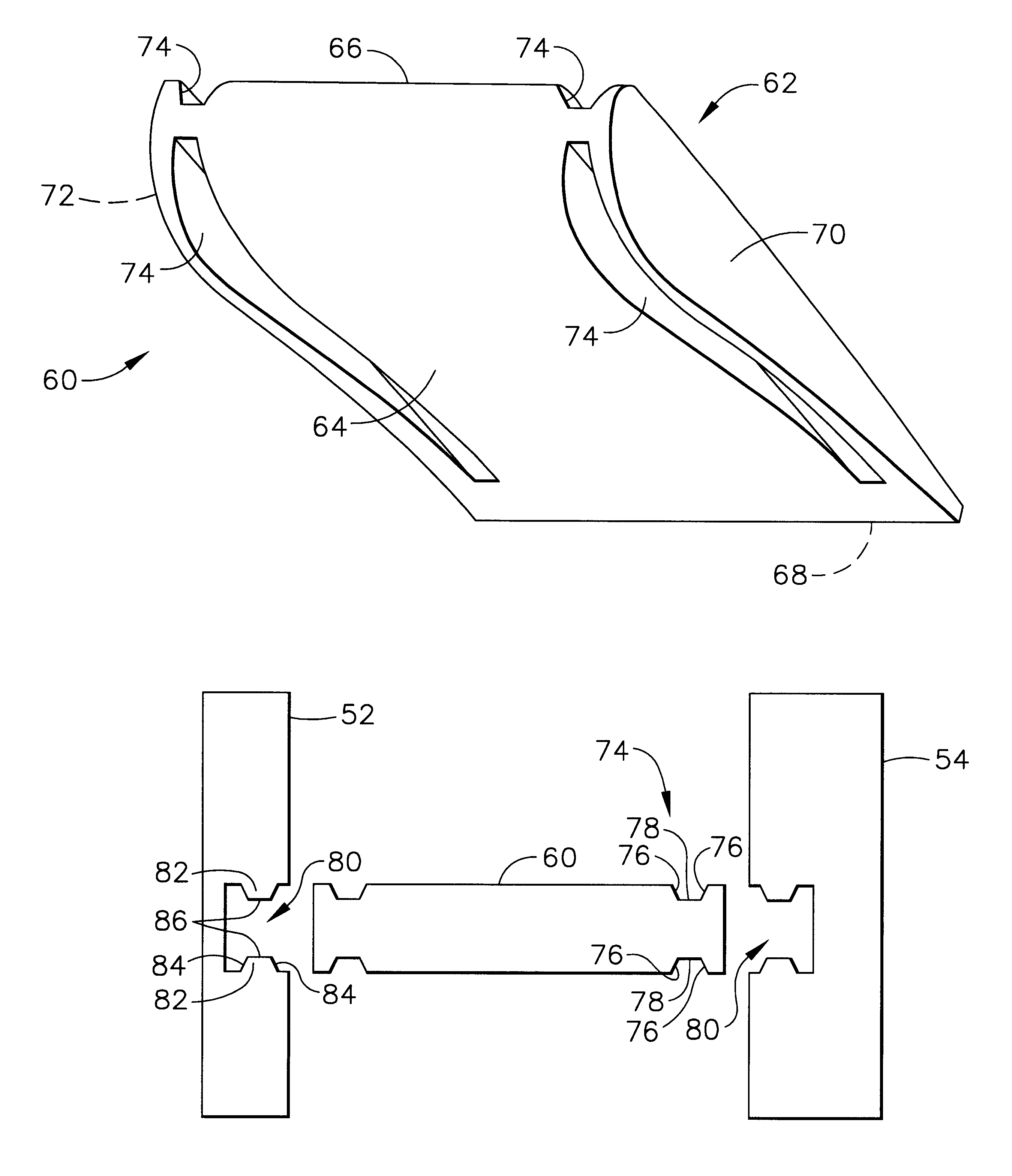
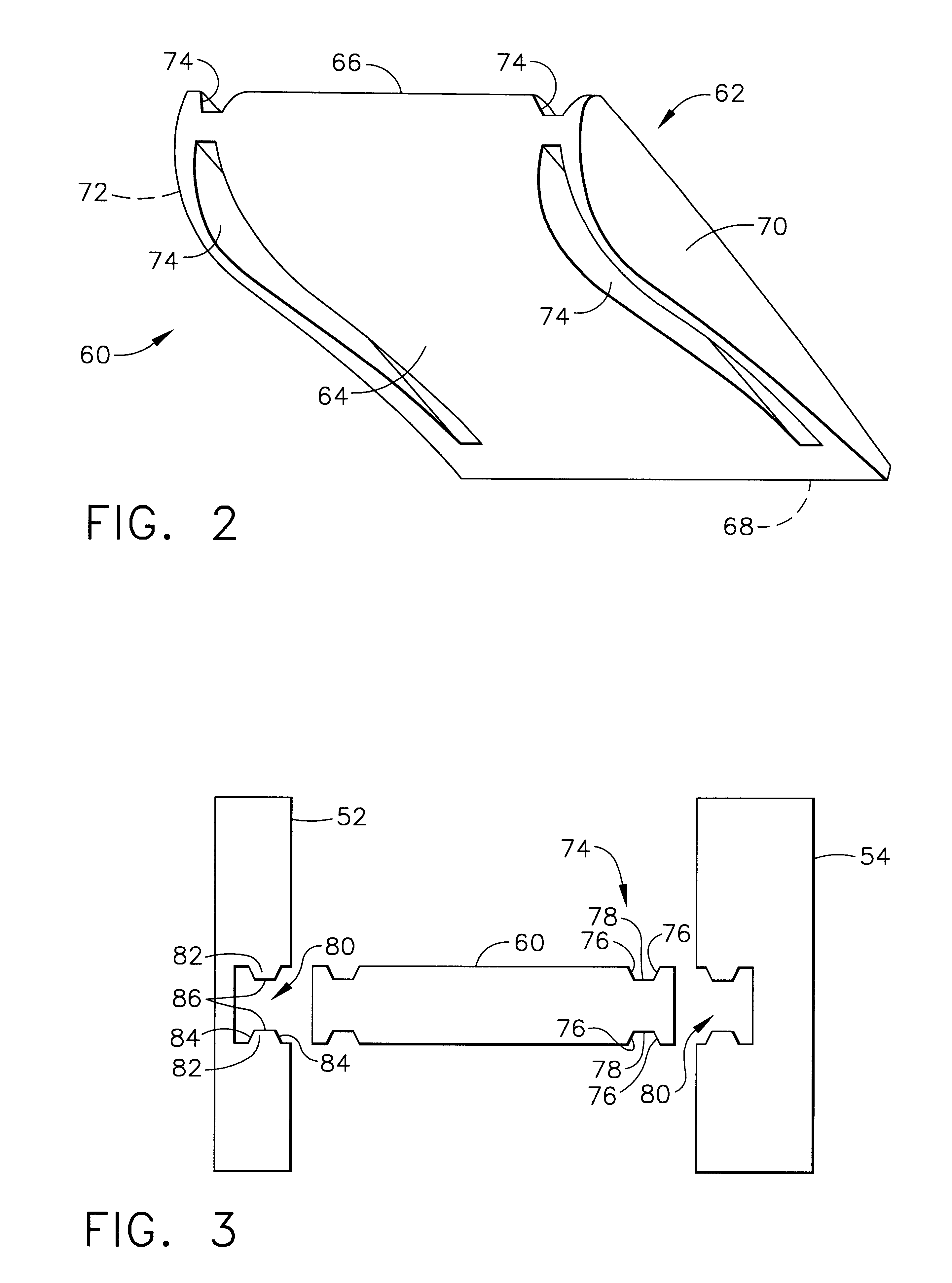
The dogbone shaped connectors between the vane and the walls generates a very low stress condition in the ceramic vane. This allows for local thermal growth differentials associated with the casting process, engine operation and room temperature while at the same time ensuring positive contact of the vane at engine operation to prevent vibration or other functional problems associated with loose vanes.

Problems solved by technology

Historically, these temperatures have been limited by the materials, usually high temperature steel or nickel alloy, used to form the first stage stator vanes.
A problem that has arisen in casting ceramic vanes to metal casings or housings is the need to accommodate the large thermal growth mismatch between the ceramic and the metal.
If not dealt with properly, this mismatch will induce stress levels in the vanes and casing that may lead to a failure of a part during service.

Method used


Image

  • Low stress connection methodology for thermally incompatible materials
  • Low stress connection methodology for thermally incompatible materials
  • Low stress connection methodology for thermally incompatible materials

Examples


Embodiment Construction

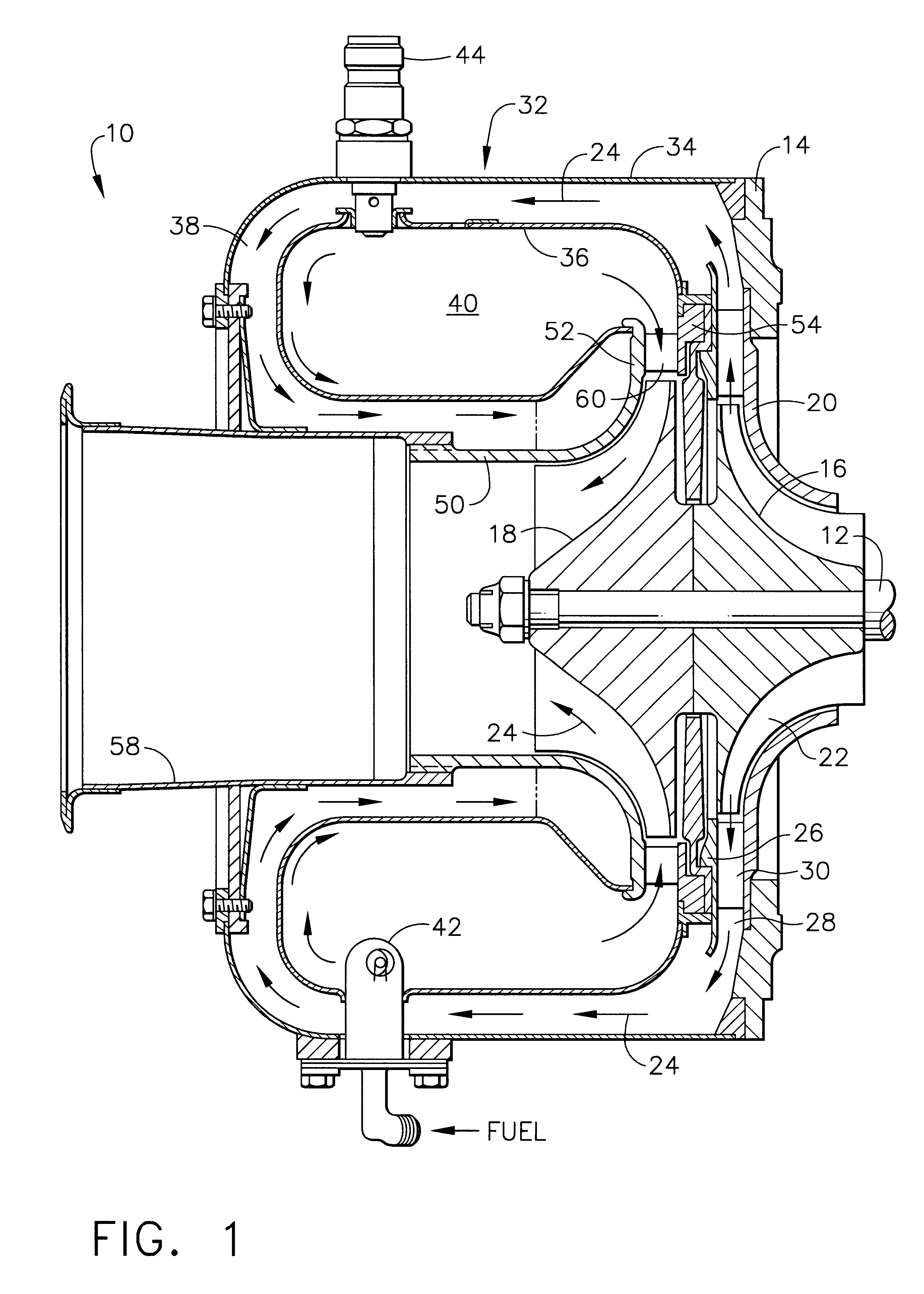
Referring to the drawings, FIG. 1 shows a gas turbine engine generally denoted by reference numeral 10. The engine type selected for illustrating the invention is an engine having a centrifugal compressor and a radial turbine. It should be appreciated that the invention is equally applicable to other type of engines such as those having axial compressors and axial turbines. The engine 10 has a rotor assembly including a shaft 12 journaled for rotation inside a casing 14. Mounted to the shaft is a compressor rotor 16 and a turbine wheel 18. The casing 14 includes a compressor housing portion 20 circumscribing an impeller 22 which is disposed within a flow path represented by the arrows 24. Axially spaced apart from the housing portion 20 is an annular wall 26 that together define a diffuser passageway 28. Disposed across the diffuser passageway 28 are a plurality of circumferentially disposed diffuser vanes 30.

From the diffuser vanes 30 compressed air flows into a reverse flow annula...


PUM

PropertyMeasurementUnit
Shapeaaaaaaaaaa
Stress optical coefficientaaaaaaaaaa

Abstract

An assembly comprising a ceramic vane with a metal housing cast around the ends of the vane. The ceramic vane has dovetailed shaped grooves along its edges that extend from the vane's leading edge to its trailing edge. The housing is comprised of two spaced apart walls each having dovetailed protrusions for mating with the dovetail grooves in the vanes's edges. Upon the casting of the walls to the vane at least one surface of each dovetail groove comes in contact with at least one surface of the dovetail protrusion. A crushable coating is disposed between the vane's edges and the dovetail protrusions.

Description

TECHNICAL FIELDThis invention relates generally to turbine vanes in gas turbine engines and a bicast assembly of a ceramic vane to a to metal housing.BACKGROUND OF THE INVENTIONIt has long been recognized that the efficiency and performance of gas turbine engines could be improved by increasing the temperature of the gas through the turbine section. Historically, these temperatures have been limited by the materials, usually high temperature steel or nickel alloy, used to form the first stage stator vanes. To permit higher gas temperatures it has been proposed to form the first stage stator vanes from a high density, high strength, silicon nitride, or silicon carbide ceramic which can withstand higher temperatures than steels or nickel alloys. However, the use of ceramic stator vanes necessitates a ceramic-to-metal interface at which the difference in thermal expansion between the ceramic vane and the metallic support structure must be accommodated so that the vanes remain fixed rel...

Claims


Application Information

Patent Timeline
IPC IPC(8): C04B37/02F01D5/00F01D5/30F01D5/12F01D5/22
CPCF01D5/225F01D5/3084F01D5/3092F05D2300/50212F05D2230/90
Inventor CHEN, E-JUNESCHENK, BJOERNBAPAT, RAMESHFOWKES, I. GENEGRACIAS, BRIANCHEN, SHEN-YEHKU, TAISONPALUCH, II, JOSEF
Owner HONEYWELL INT INC
Learn More