
Filtration device for liquid purification

a filtration device and liquid purification technology, applied in the direction of filtration separation, separation process, treatment involving filtration, etc., can solve the problems of significantly reducing the filtration capacity of the filter, visual control of the work of the filter, and insufficient resistance of the filter to the liquid flow, so as to confirm the effect of the invention

Inactive Publication Date: 2002-05-14
ELECTROPHOR INC
View PDF8 Cites 76 Cited by
  • Summary
  • Abstract
  • Description
  • Claims
  • Application Information

AI Technical Summary

Benefits of technology

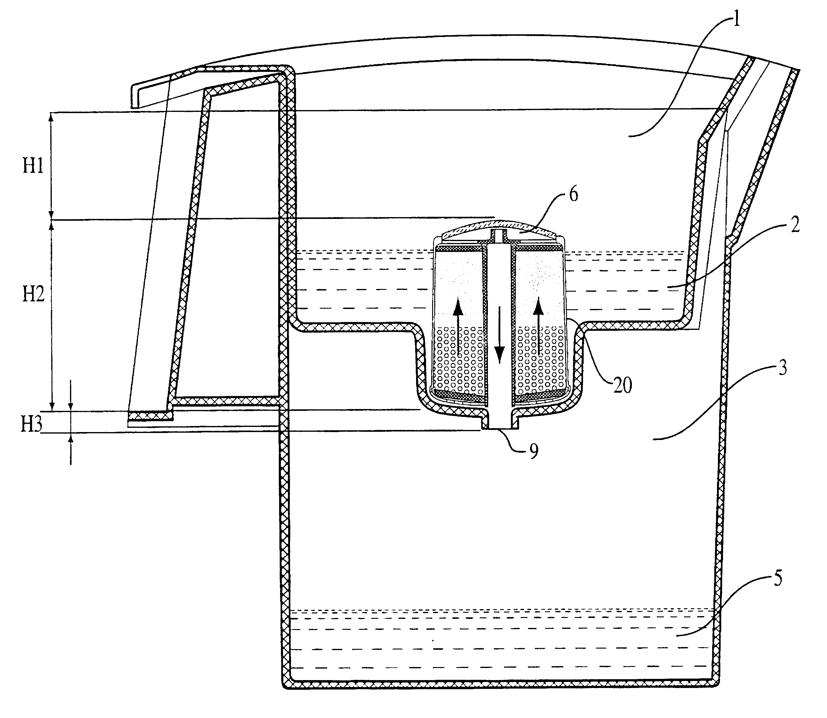
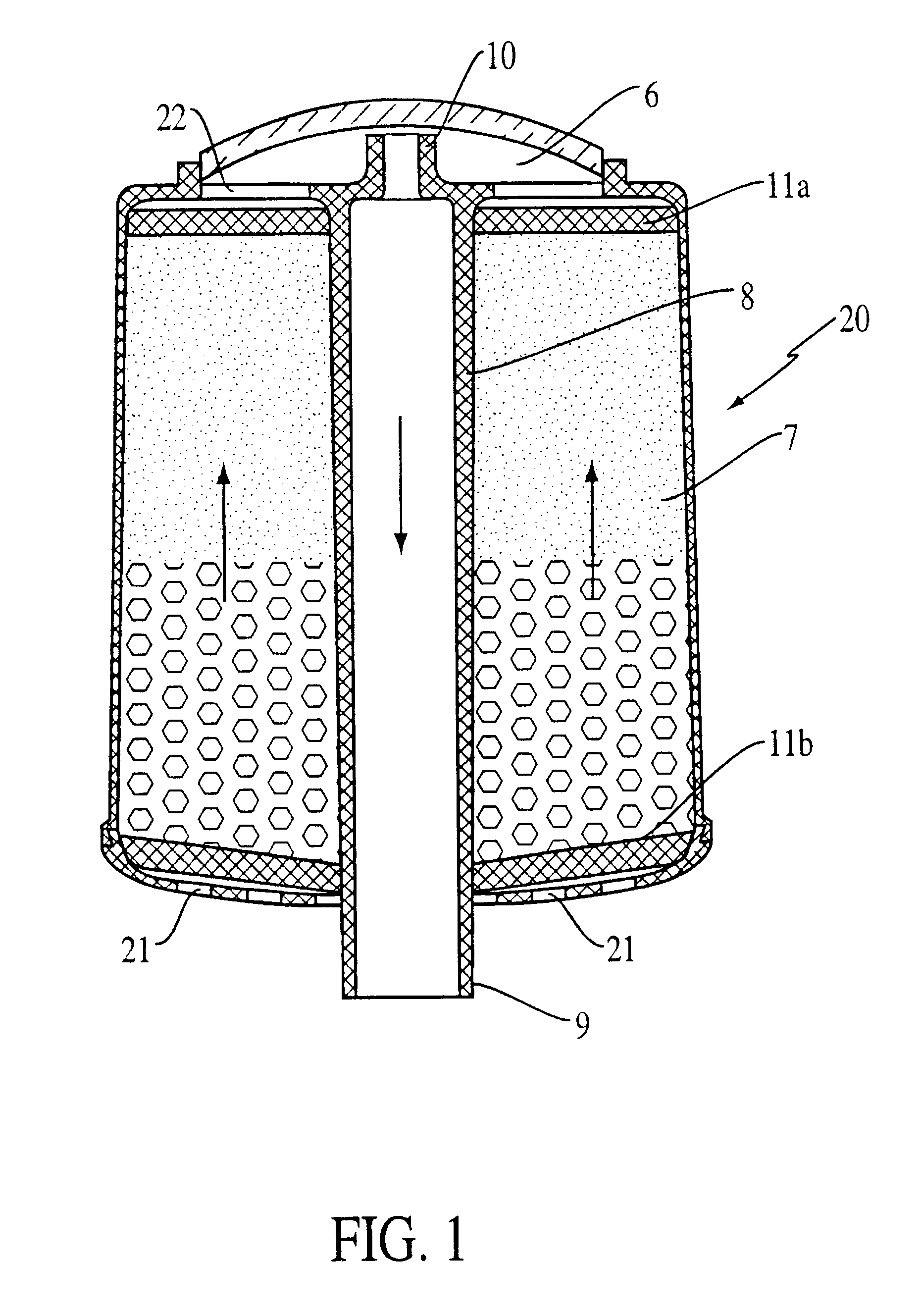
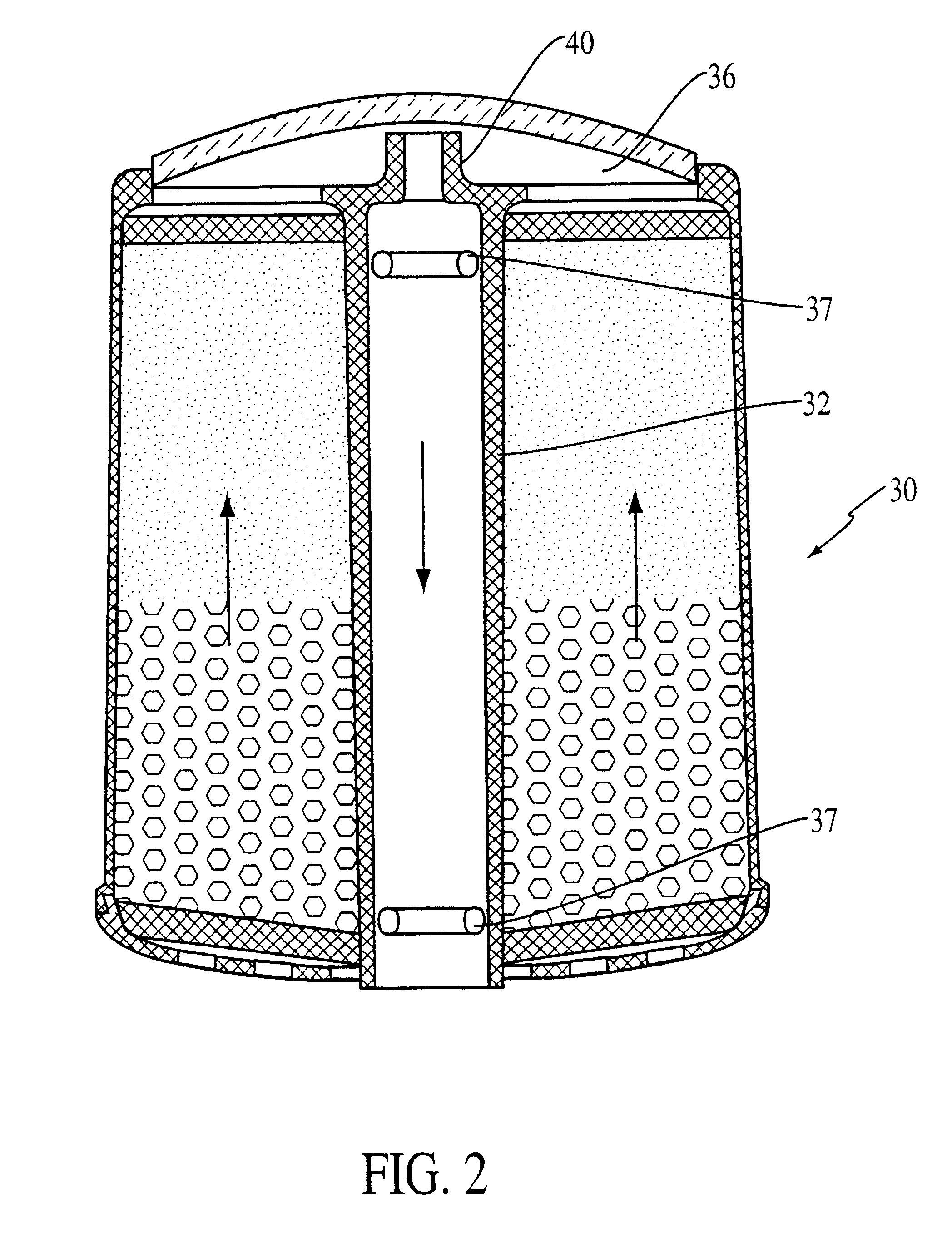
Comparison tests are performed between filters with the identical adsorption capacities, but in the first case (as suggested by the present invention) in the upward flow direction, and in the second case (as suggested by the prior art) in the downward flow direction. It is done in order to confirm effectiveness of the invention by comparing results of purifying different solutions through the filters. Conditions and results of the experimental investigation of the effectiveness of the invention and also experimental proof that it is possible to obtain a new technical result are shown in Examples 1, 2, 3 and 4 and Tables 1 and 2.
by comparing results of purifying different solutions through the filters. Conditions and results of the experimental investigation of the effectiveness of the invention and also experimental proof that it is possible to obtain a new technical result are shown in Examples 1, 2, 3 and 4 and Tables 1 and 2.

Problems solved by technology

As medical and ecological information has increasingly shown that water pollution leads to illnesses, and as pollution of natural water resources, caused at least in part by population growth, has also increased, it has become obvious that it is necessary to use purified drinking water.
Currently used filters employing granular adsorbents do not completely provide adequate resistance against the liquid flow.
Plugging of the end filter significantly reduces the filtration capacity of the filter.
Another problem is the visual control of the work of the filter, and controlling the quantity of the liquid that is being filtered.
Prior art filters are subject to another problem.
These bubbles block pores, making liquid flow through the filter more difficult.
This makes the filters more complicated and expensive, and limits the possible scope of their use.
Another significant drawback of known filter designs, wherein filtration takes place by the downward flow caused by gravity, is a complete drying out of the filter after the end of the filtration process.
This limits the selection of ion-exchange materials that can be employed as filtration and adsorption agents, because many can not stand up to the periodically changing drying and wetting conditions, and they cease to perform properly.
Construction of such a filter element is difficult.
Furthermore, filtration takes place by the "channeling flow," wherein liquid is being filtered through the filtration material non-uniformly along the separate channels.
Known filters wherein filtration takes place in the downward direction either require using pressure from the water tap line (which limits where the filter can be used), or require hydrostatic pressure of an additional column of liquid (which does not purify the entire liquid volume, due to loss of pressure from the additional column of liquid), or require using additional complicated fixtures and constructions for effecting filtration.
Attempts to solve these problems in the known designs have led either to more complicated and expensive constructions or to the incomplete purification of at least a part of the liquid that is being filtered.

Method used


Image

  • Filtration device for liquid purification
  • Filtration device for liquid purification
  • Filtration device for liquid purification

Examples


example 1

There are compared two water filters with the identical interval volumes. Each filter contains 90 ml of the adsorbing carbon material. This adsorbing carbon material comprises AQUALEN activated carbon fiber (manufactured by Aquaphor Corporation, St. Petersburg, Russia) and granular activated carbon G55C-8 (manufactured by PICA Corp., USA) in a weight by weight ratio of 1:7 (4.8 g of Aqualen, dry weight, and 33 g of granular carbon). In one of the filters the water flows downwardly (as in the prior art) and in the second filter water flows in an upward direction according to the present invention. The time to flow 1 liter of liquid is 15 minutes. Phenol solution with a concentration of 10 mg / L was used as the test solution. The comparison results are shown in Table No. 1.

example 2

The experimental conditions are the same as in Example 1 except that a solution containing E. Coli index 100 (100 E. Coli bacteria per 1 liter) was used. Results of the experiment are shown in Table No. 1.

example 3

The experimental conditions are the same as in Example 1 except that a cation-exchange resin SR-10 (manufactured by SYBRON Corp., USA) in the amount of 90 grams was used. The time for flowing 1 liter of liquid was 4 minutes 3 seconds. Copper solution (10 mg / g) is used as a model Solution. Experimental results are shown in Table No. 1.


PUM

PropertyMeasurementUnit
Fractionaaaaaaaaaa
Densityaaaaaaaaaa
Densityaaaaaaaaaa

Abstract

The invention is directed to purification of liquids, such as drinking water using filters, wherein filtration is effected while the liquid flows upwardly. The invention includes both the method and a device enabling the method to be carried out. The device is constructed to intake impure liquid at the bottom of the filter and initially to effect flow by filling liquid to above the filter outlet near the top, and maintaining flow thereafter by virtue of the presence of a low internal pressure that develops as the liquid passes through the system.

Description

The present invention relates to the purification of liquids such as water; and, more particularly, to improved purification devices wherein liquid flow is initiated by gravity through a filter containing an adsorption-bactericidal material, and the flow continues without using any additional sources of external pressure. Use of the improved device causes a flow pattern of liquid passing therethrough of such nature that the adsorption and bactericidal purification is enhanced and the quality of the purified liquid is thereby significantly higher than heretofore available.As medical and ecological information has increasingly shown that water pollution leads to illnesses, and as pollution of natural water resources, caused at least in part by population growth, has also increased, it has become obvious that it is necessary to use purified drinking water. The public clearly demands that the quality of its drinking water must be improved to ever greater levels. The need to filter water...

Claims


Application Information

Patent Timeline
IPC IPC(8): B01J47/02B01J47/00C02F1/00C02F1/42C02F1/50C02F1/28
CPCB01J47/002B01J47/024C02F1/003B01J20/20C02F1/42C02F1/283C02F1/50C02F2201/006C02F2307/04B01J47/012
Inventor PIMENOV, ALEXANDER V.RUSINOV, GLEBSHMIDT, JOSEPH L.LIEBERMAN, ALEXANDER I.
Owner ELECTROPHOR INC
Learn More