
Synchronization detection device and its method

a detection device and synchronization technology, applied in the direction of synchronization arrangement, amplitude demodulation, multiplex communication, etc., can solve the problem of longer time required for cell search

Inactive Publication Date: 2002-05-07
SONY CORP
View PDF6 Cites 63 Cited by
  • Summary
  • Abstract
  • Description
  • Claims
  • Application Information

AI Technical Summary

Problems solved by technology

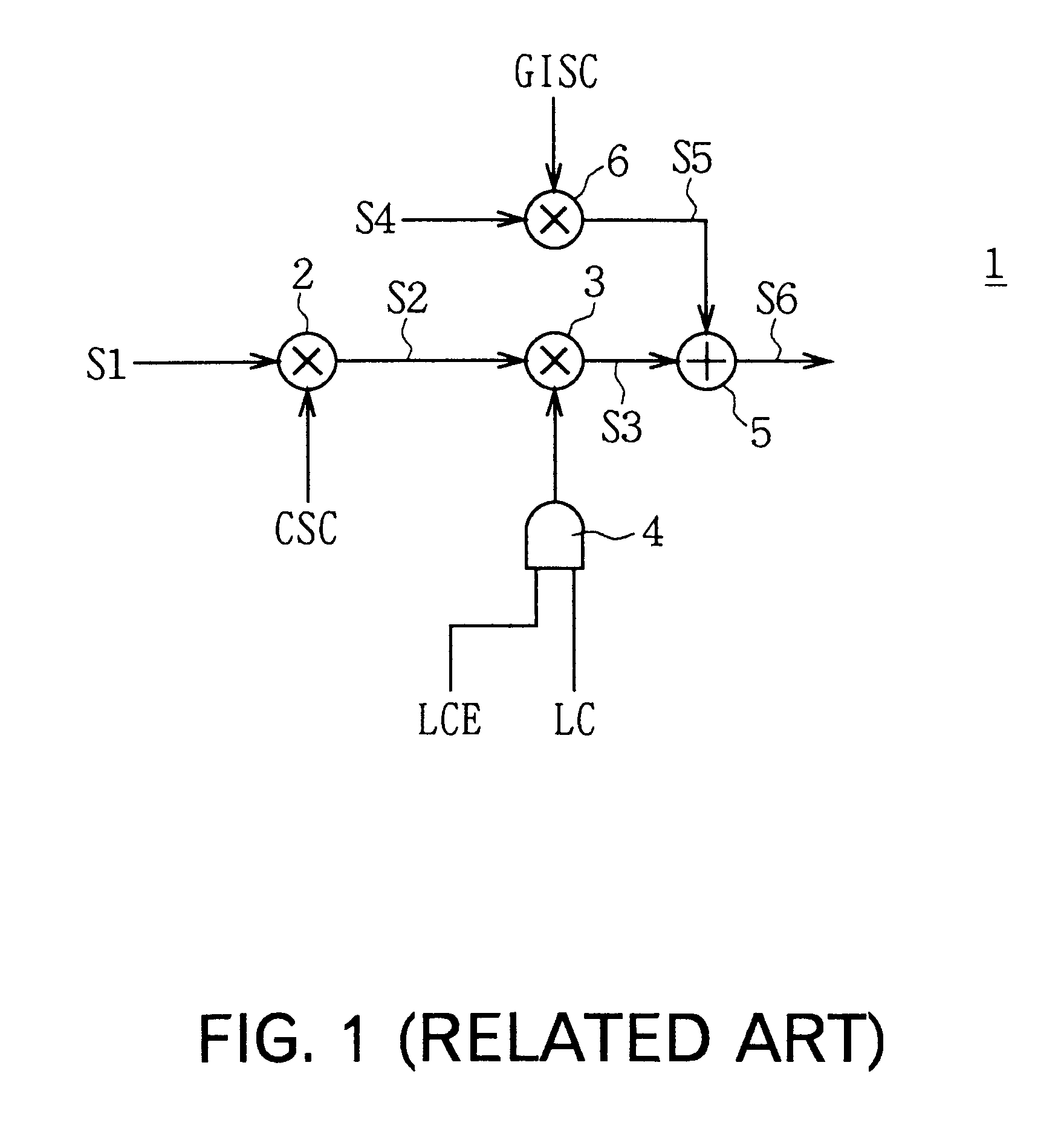
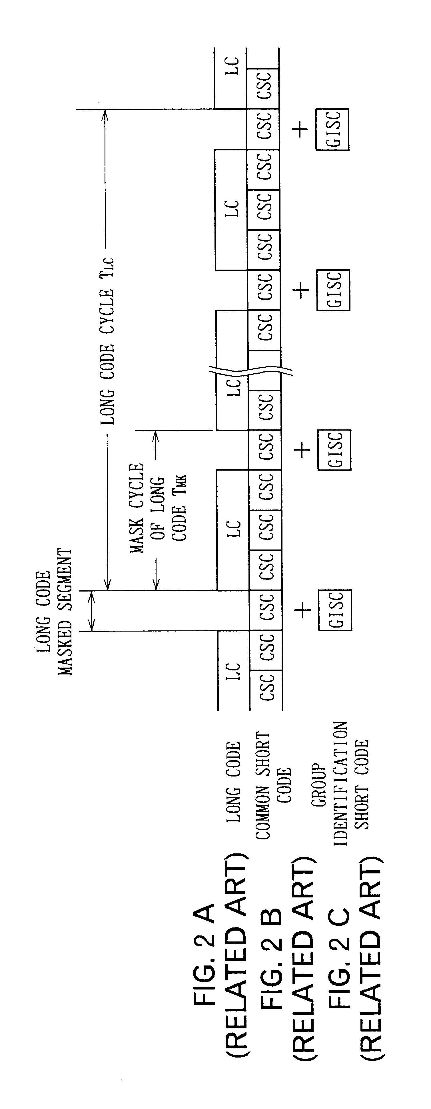
Therefore, in the case of asynchronous system between base stations, there is a problem that the time required for cell search becomes longer as compared with the synchronous system between base stations.

Method used


Image

  • Synchronization detection device and its method
  • Synchronization detection device and its method
  • Synchronization detection device and its method

Examples


first embodiment

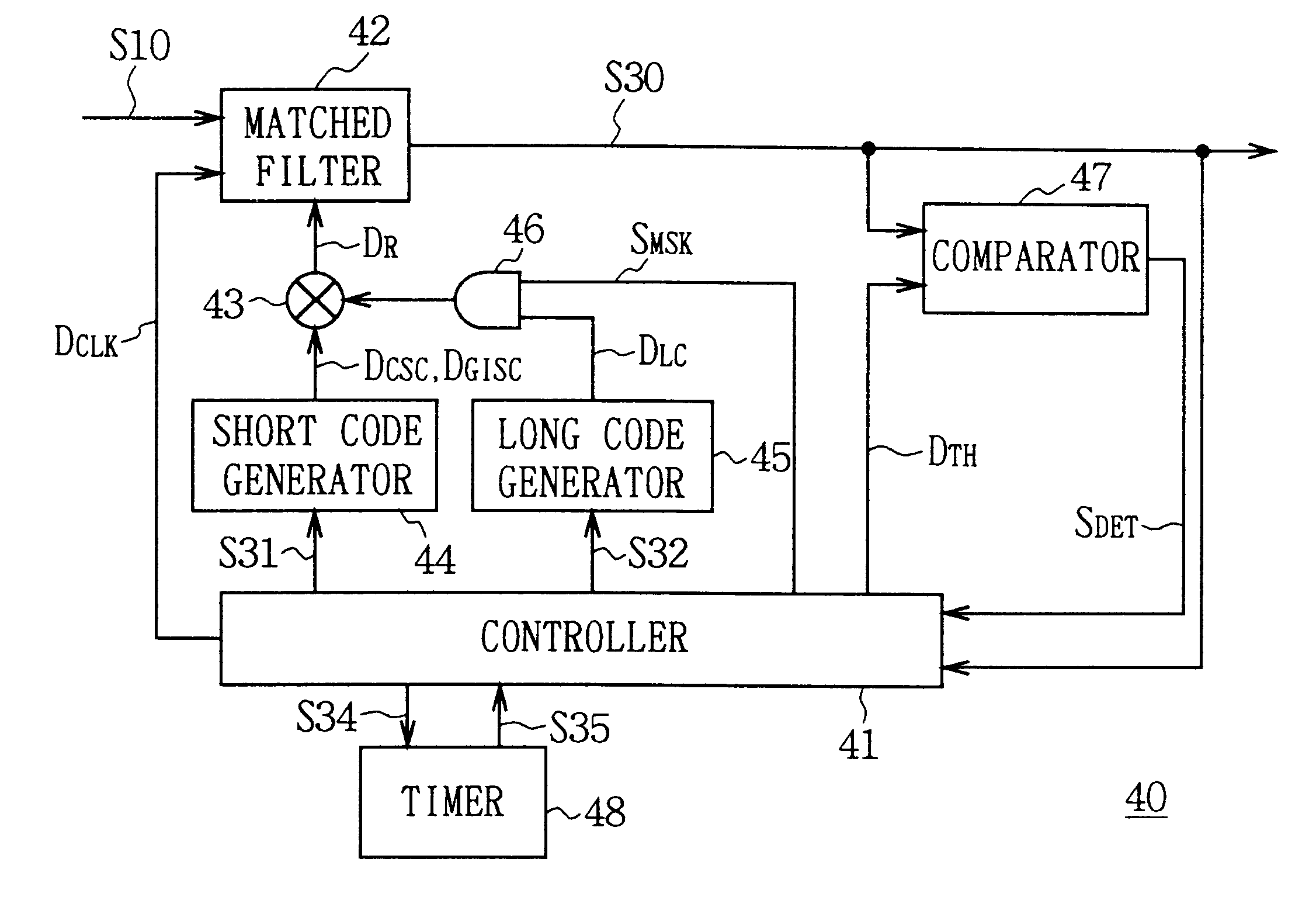
In FIG. 5, 40 generally shows a synchronization detection device and by controlling each circuit block with a controller 41, identifies the long code LC included in the received signal S10 at high speed. In this case, it is supposed that the long code LC, common short code CSC and group identification short code GISC are included in the received signal S10 at the timing shown in FIGS. 2A to 2C.

First, as shown in FIG. 6, a matched filter 42 comprises the same number of stages of shift registers 42A as the number of chips of common short codes CSC, coefficient multiplier 42B having the same number of multipliers as the number of stages of the shift registers 42A, and a combining circuit 42C for combining the multiplication results to be transmitted from the multipliers of the coefficient multiplier 42B, in which a bit string of received signal S10 is sequentially input to the shift register 42A. Also the shift register 52A receives the operation clock DCLK from the controller 41 and ...

second embodiment

Next, a synchronization detection device of this invention will be described.

In FIG. 14, 80 generally shows a synchronization detection device according to this embodiment, and long code LC included in the received signal S10 is identified at high speed by controlling each circuit with a controller 81.

Also in the case of this embodiment, the received signal S10 is entered into the matched filter 82, and the matched filter 82 sequentially enters that received signal S10 into the internal shift register based on the data shift clock D.sub.CLK1 supplied from the controller 81. Then, the matched filter 82 sequentially calculates the correlation value S60 between each bit of the received signal S10 captured and the replica code D.sub.R to be correlation-detected that is generated in the correlation coefficient generator 83, and transmits these to the controller 81, latch circuit 84 and adder 85.

The correlation coefficient generator 83 generates replica code D.sub.CSC of the common short...


PUM


Abstract

Codes to be detected can be identified at high speed. The supply of the data shift clock (DCLK1) to be given to the matched filter (82) is stopped at desired timing to hold the received signal (S10) and replica code generated at the correlation coefficient generator (83) is switched to the first, second or third replica code at desired timing to detect the correlation value of that time. Thereby, the second code, the third code and the first code are detected in order to detect the timing and the code type of the first code. Therefore, each correlation detection can be conducted at the same timing since the matched filter conducts the correlation detection at high speed holding the received signal and thus, the first code included in the received signal can be identified at higher speed than before.

Description

1. Field of the InventionThis invention relates to a synchronization detection device and its method, and more particularly, is suitably applied to a cellular radio communication system that allows asynchronous communication between base stations according to the direct sequence-code division multiple access (DS-CDMA) system.2. Description of the Related ArtThe DS-CDMA system is a multiplexing system using spread codes and its application to the cellular radio communication system has been vigorously under study as one of the radio access systems of the future mobile communication system. In the cellular radio communication system, an area to provide communication service is divided into cells with a desired size and a base station as a fixed station is provided in each cell and a communication terminal device which is a mobile station is connected by radio to the base station having the best communication state.In such a cellular radio communication system, a method to search a bas...

Claims


Application Information

Patent Timeline
IPC IPC(8): H04B1/707H04B1/7075H04B1/7085H04L7/00H04B1/7093H04W56/00H04W92/00
CPCH04B1/7075H04B1/7077H04B1/7093H04B2201/70707H04B1/7083
Inventor TERASHIMA, KAZUHIKO
Owner SONY CORP
Learn More