Loop antenna parasitics reduction technique
a parasitic reduction and loop antenna technology, applied in the field of antennas, can solve the problems of lowering the antenna performance, significant losses, and inability to achieve optimal radiation, and achieve the effects of reducing the serial resistance of the antenna, and increasing the efficiency of the antenna
- Summary
- Abstract
- Description
- Claims
- Application Information
AI Technical Summary
Benefits of technology
Problems solved by technology
Method used
Image


Examples
Embodiment Construction
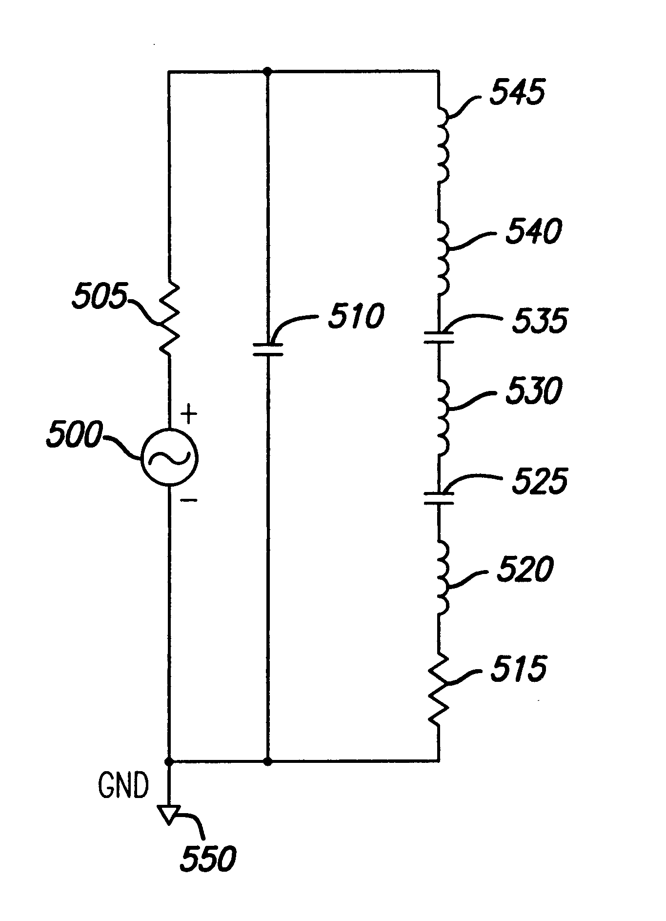
cm (calculated by 2 * (length+width)). Given L.sub.a equals 0.6 uH and C.sub.X equals 18 pf, x / L equals 0.845. Multiplying this result by L then yields 16.892 cm. Thus, C.sub.X should be placed 16.892 cm from the GND end of L.sub.a.
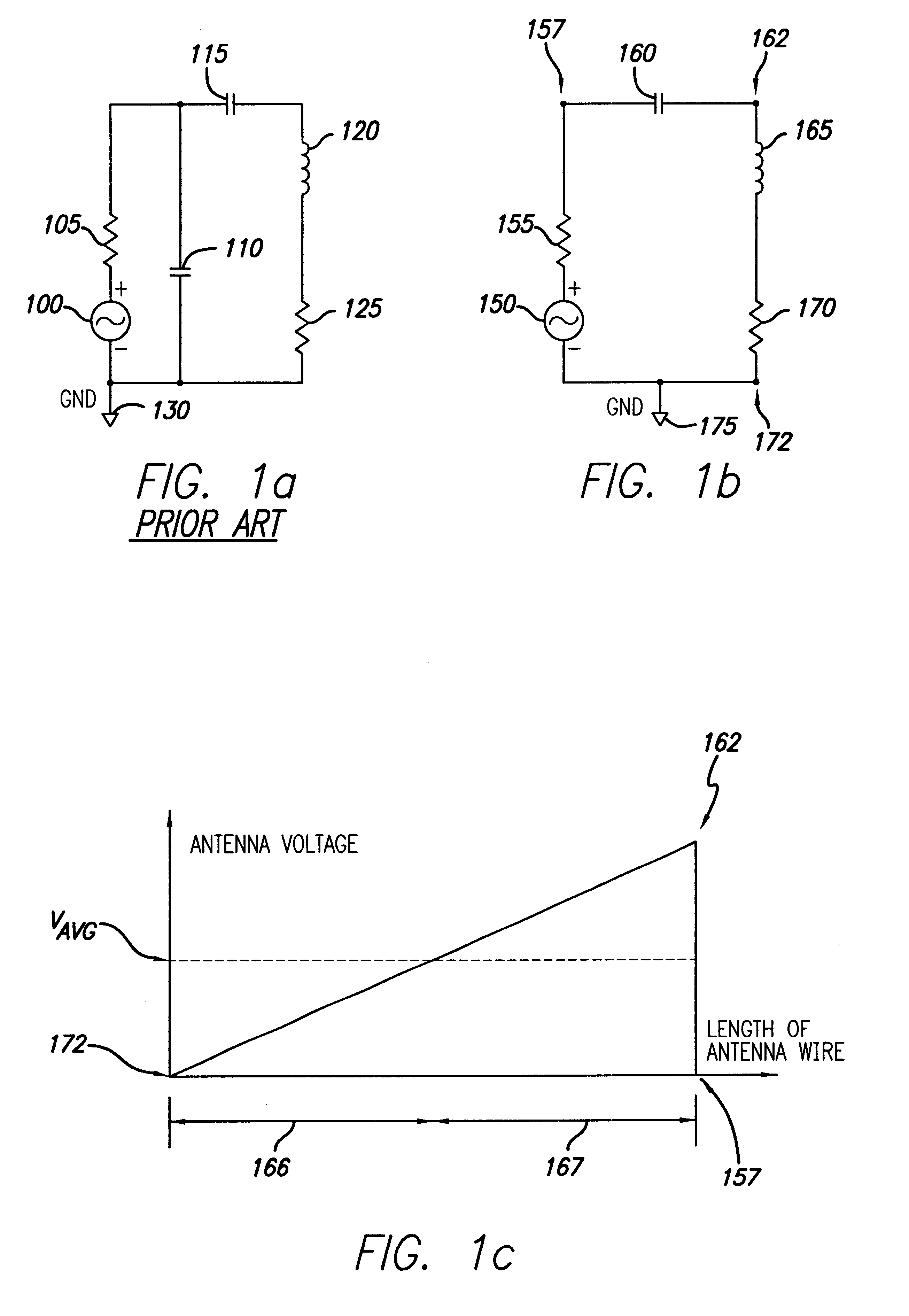
FIG. 4a is an electrical schematic of yet another antenna matching circuit in accordance with the present invention. A two-turn conductor, comprised of loop segment 420 (loop turn number one) and loop segment 435 (loop turn number 2), and resistor 425 represent the antenna portion of the circuit. Resistor 425 symbolizes the overall resistance of the antenna at its operating frequency. Source 400, along with source resistance 405, are simply provided to energize the circuit. As can be seen, there are four tuning capacitors, capacitor 410, capacitor 415, capacitor 440 and capacitor 430. Capacitor 415 is serially connected to the outer end of loop segment 420. Capacitor 440 is connected to outer end of loop segment 435. Capacitor 430 is connected between the...
PUM
 Abstract
Description
Claims
Application Information
 - R&D
- Intellectual Property
- Life Sciences
- Materials
- Tech Scout
- Unparalleled Data Quality
- Higher Quality Content
- 60% Fewer Hallucinations
Browse by: Latest US Patents, China's latest patents, Technical Efficacy Thesaurus, Application Domain, Technology Topic, Popular Technical Reports.
© 2025 PatSnap. All rights reserved.Legal|Privacy policy|Modern Slavery Act Transparency Statement|Sitemap|About US| Contact US: help@patsnap.com