
Vehicle seat assembly comprising a removable seat assembled on guide rails

a technology of vehicle seat and guide rail, which is applied in the direction of movable seats, roofs, furniture parts, etc., can solve the problems of increasing the cost of the seat assembly and significant constraints on the seat design, and achieve the effect of preventing the separation of the first foot from the vertical

Inactive Publication Date: 2002-03-19
BERTRAND FAURE EQUIP SA (FR)
View PDF29 Cites 50 Cited by
  • Summary
  • Abstract
  • Description
  • Claims
  • Application Information

AI Technical Summary

Benefits of technology

Moreover, the anchoring of the seat foot is made directly on the fixed section, which reinforces the solidity of the anchoring of the seat on the vehicle floor.
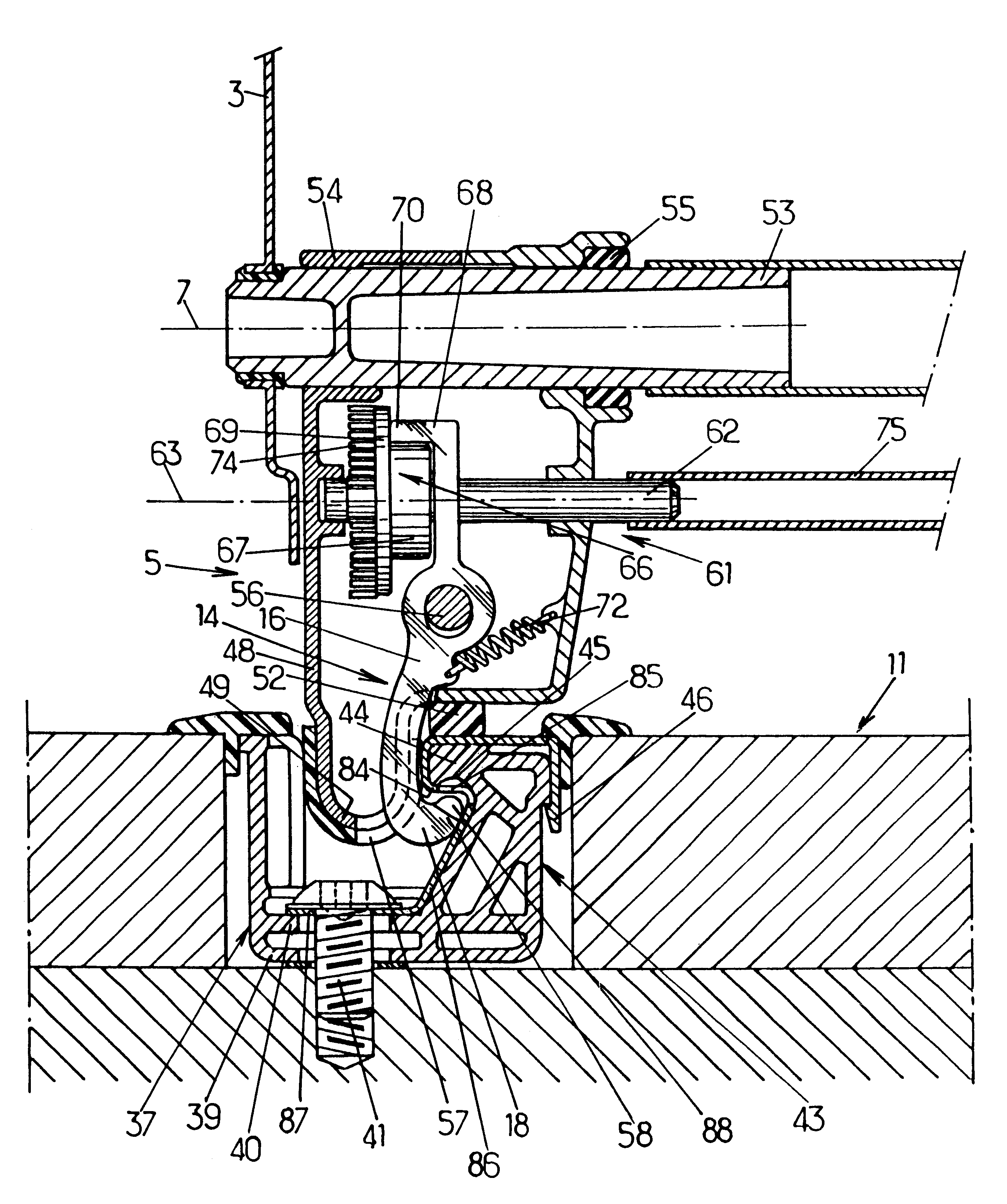
Furthermore, the guide rail movable section is totally eliminated, which decreases the cost of the seat assembly. Thus, the guide rail of the seat assembly according to the invention has a size reduced to the absolute minimum and does not give any discomfort to the vehicle passengers when the seat is removed. In the preferred embodiments of the invention, recourse may possibly by had moreover to one and / or other of the following arrangements as described below. In one embodiment, the first jaw part may be adapted to cooperate with the fixed section to prevent longitudinal movement of the seat when the coupling lock is in its locked position. The control device may be adapted to raise the first jaw part to apply the coupling claw of the first jaw part under the longitudinal edge of the fixed section, with clamping, when the first jaw part is in its locked position, thereby preventing longitudinal movement of the seat. The fixed section may include notches which are arranged under the longitudinal edge of said fixed section and the coupling claw may have upwardly directed teeth which are adapted to engage in the notches when the coupling lock is in its locked position, thereby preventing longitudinal movement of the seat. The control device may be adapted to move the coupling lock between the locked position, the withdrawn position, and an intermediate position where the first jaw part is in a sliding position and where the coupling claw of said first jaw part protrudes under the longitudinal edge of the fixed section, thereby preventing vertical separation of said first foot from the fixed section, but where the first jaw part is sufficiently separated from the fixed section to enable longitudinal movement of the seat. The control device may include a transverse control shaft which is pivotally mounted relative to the seat and which is movable between first and second positions corresponding respectively to the locked and withdrawn positions of the coupling lock.

Problems solved by technology

This requirement causes significant constraints on the seat design, particularly if it is desired to assemble the seat facing towards either the front or rear of the vehicle.
Moreover, the seat assembly described in the aforementioned document as also the disadvantage that the restraining forces of the seat are passed through the movable section: this imposes a sufficient sizing of this movable section and its connections with the seat and with the fixed section, which tends to again increase the cost of the seat assembly.

Method used


Image

  • Vehicle seat assembly comprising a removable seat assembled on guide rails
  • Vehicle seat assembly comprising a removable seat assembled on guide rails
  • Vehicle seat assembly comprising a removable seat assembled on guide rails

Examples


Embodiment Construction

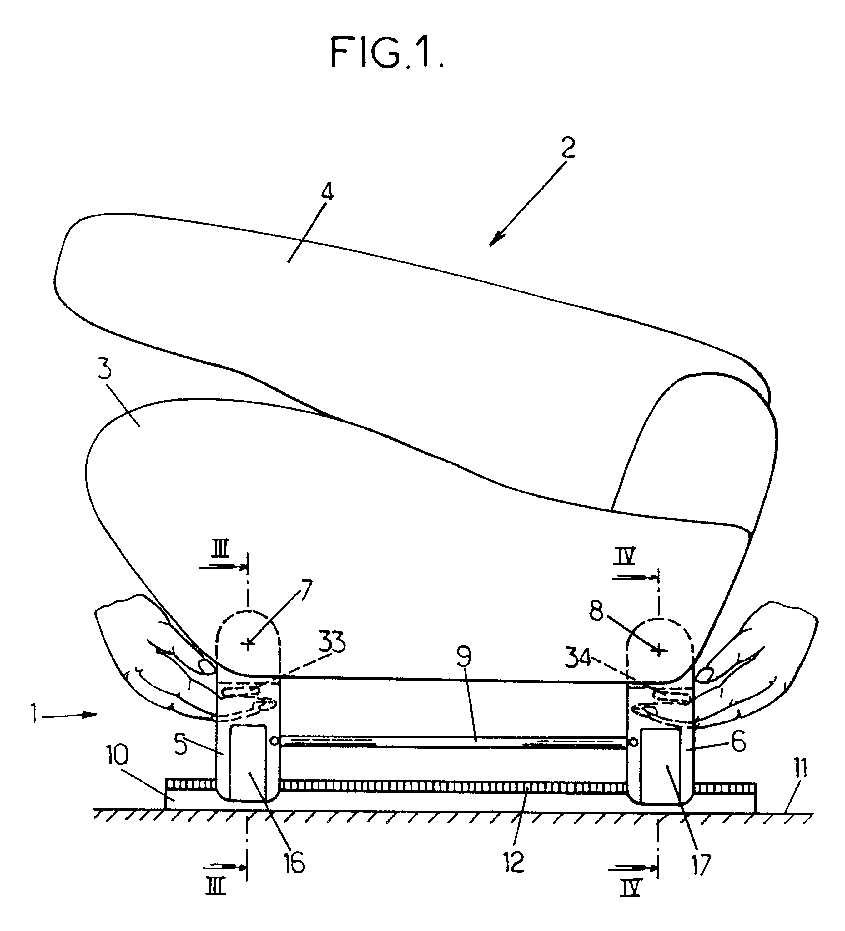
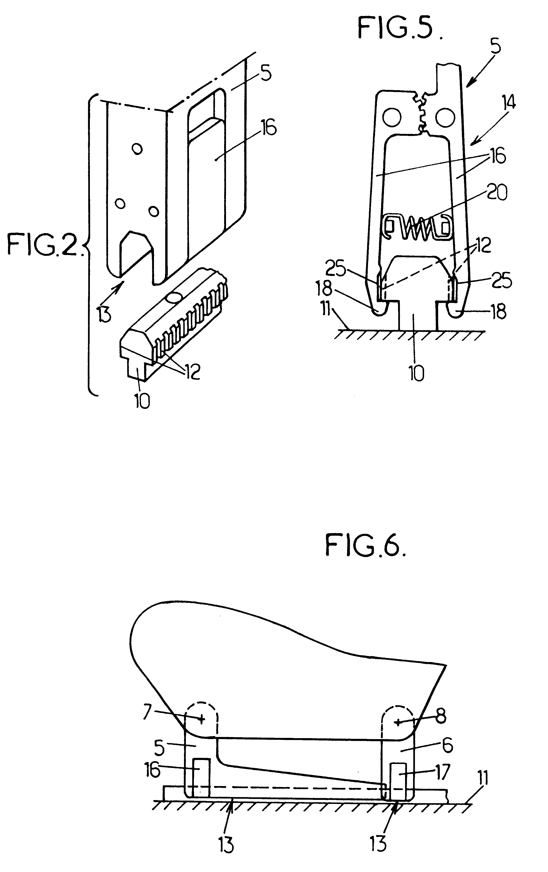
In the different figures, the same references designate identical or similar components. FIG. 1 shows a vehicle seat assembly 1, comprising

a seat 2 which includes a seat bottom 3 and a back 4 shown here in the frontward folded down position, the seat 3 resting on four feet, i.e. a pair of front feet 5 and a pair of rear feet 6, the front feet 5 being preferably pivoted on the seat 3 about a first transverse horizontal axis 7, the rear feet 6 being preferably pivoted on the seat 3 about a second transverse horizontal axis 8, and the front and rear feet located on the same side of the seat being preferably connected together by a horizontal rod 9 which is articulated on the two feet, for reasons which will be explained below,

and two parallel guide rails which are fixed to the vehicle floor 11 and which enable the sliding of the seat 2 frontward or backward in a so-called longitudinal direction, each guide rail supporting the two feet 5, 6 which are located on the same side of the seat...


PUM


Abstract

A vehicle seat the feet of which are assembled in a removable manner on two fixed sections by means of vertical jaws which ensure the coupling of the seat onto the fixed sections.

Description

The present invention relates to seat assemblies for vehicles, comprising a removable seat assembled on guide rails.More particularly, the invention concerns a vehicle seat assembly, comprising:at least one first guide rail including a fixed section which is intended to be integral with the vehicle floor and which extends in a longitudinal direction, said fixed section comprising a longitudinal edge, and a seat having at least one first foot which is assembled in a removable manner on the guide rail to enable the seat to be vertically detached from the guide rail, said first foot comprising a coupling lock which is movable between a locked position where said coupling lock engages with the guide rail to make said first foot integral with said guide rail and a withdrawn position where said first foot can separate vertically from the guide rail, said seat having control means for moving said coupling lock between said locked and withdrawn positions.Document FR-A-2 700 735 describes an...

Claims


Application Information

Patent Timeline
IPC IPC(8): B60N2/02B60N2/005B60N2/20B60N2/015B60N2/04
CPCB60N2/01541B60N2/206B60N2205/40B60N2/00B60N2/04
Inventor BOISSET, BERNARDLEJEUNE, JEAN-MICHELSCHWARTZ, LAURENT
Owner BERTRAND FAURE EQUIP SA (FR)
Learn More