
Process for producing polyolefins

a polyolefin and polymer technology, applied in chemical/physical/physical-chemical processes, chemical apparatus and processes, bulk chemical production, etc., can solve the problems of not being able to disclose any specific reactor structure indicating how the operation of the reactor may be made more efficient, requiring a relatively high pressure to be employed, and not allowing a particularly high comonomer concentration to be employed in the reactor

Inactive Publication Date: 2002-03-12
FINA RES SA
View PDF6 Cites 125 Cited by
  • Summary
  • Abstract
  • Description
  • Claims
  • Application Information

AI Technical Summary

Benefits of technology

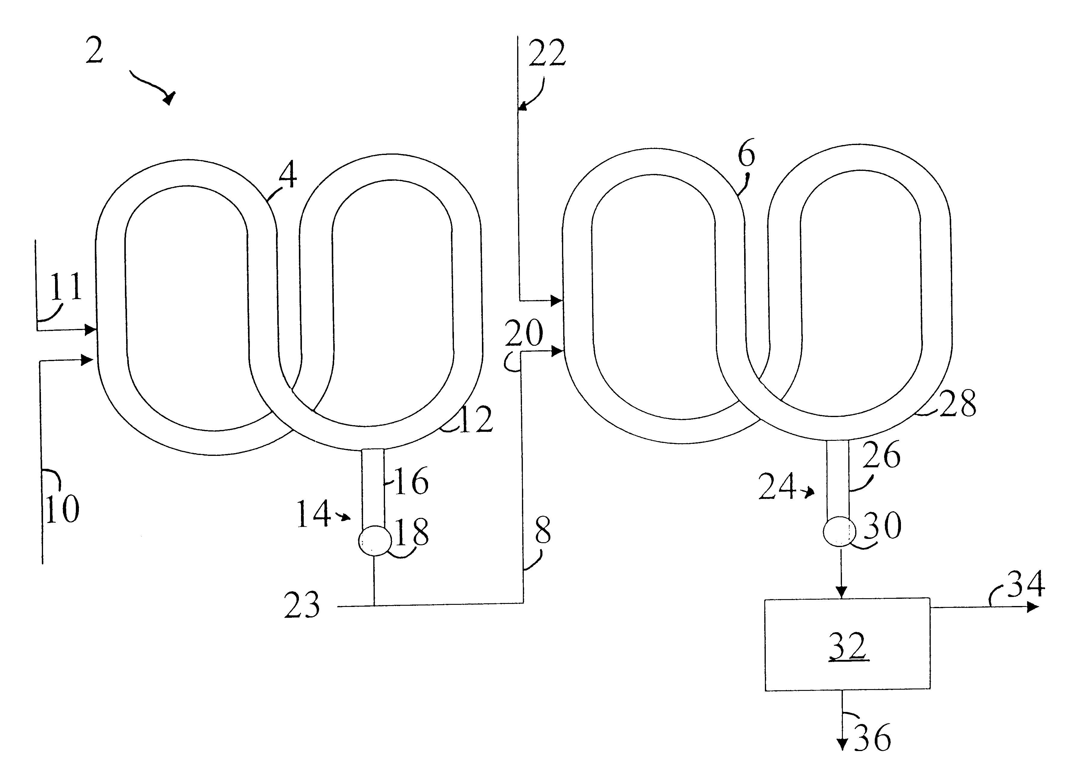
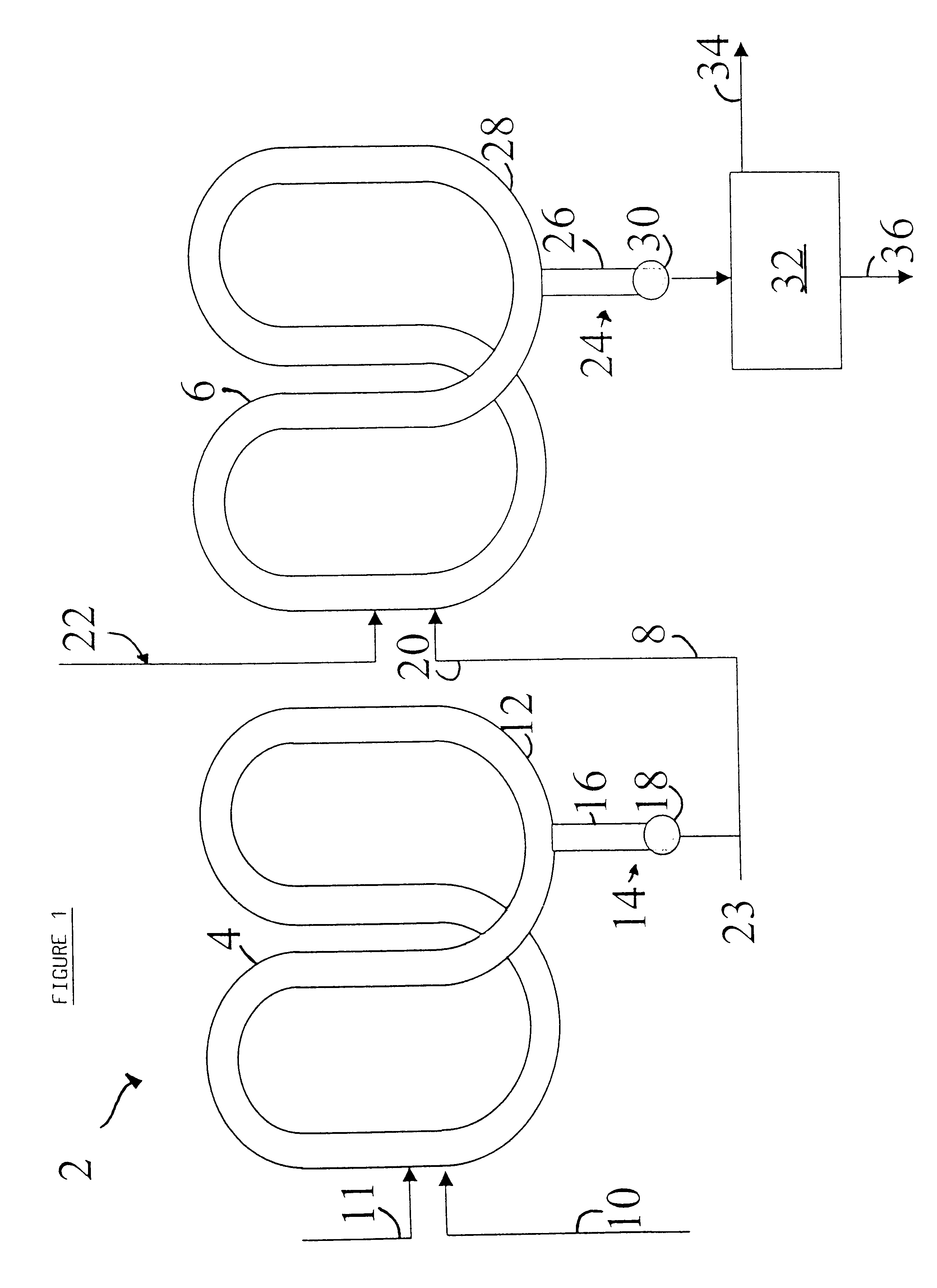
The present invention yet further provides the use, in a pair of serially connected loop reactors for polymerising ethylene in the presence of a catalyst to produce polyethylene having a bimodal molecular weight distribution and including a first polyethylene fraction comprising polyethylene copolymer produced in a first loop reactor and a second polyethylene fraction comprising polyethylene homopolymer produced in a second loop reactor downstream of the first loop reactor, of a diluent under supercritical conditions in at least the first loop reactor for reducing the amount of comonomer in solution in the diluent transferred from the first loop reactor to the second loop reactor.
The present invention also provides the use in a pair of serially connected loop reactors for polymerising ethylene in the presence of a catalyst to produce polyethylene having a bimodal molecular weight distribution and including a first polyethylene fraction comprising polyethylene homopolymer produced in a first loop reactor and a second polyethylene fraction comprising polyethylene copolymer produced in a second loop reactor downstream of the first loop reactor, of a diluent under supercritical conditions in at least the first loop reactor for reducing the amount of hydrogen in solution in the diluent transferred from the first loop reactor to the second loop reactor.
The present invention still further provides the use, in a pair of serially connected loop reactors for polymerising an olefin in the presence of a catalyst to produce a polyolefin having a bimodal molecular weight distribution and including a first polyolefin fraction produced in a first loop reactor and a second polyolefin fraction produced in a second loop reactor downstream of the first loop reactor, of a diluent under supercritical conditions in the first and second loop reactors for reducing the amount of diluent to be recycled back into the loop reactors following removal of a mixture of polyolefin fluff and diluent from a fluff concentrating device of the second loop reactor.

Problems solved by technology

However, there is no disclosure of any specific reactor structure indicating how the operation of the reactor may be made more efficient.
Moreover, the use of propane as a diluent tends to require a relatively high pressure to be employed above the critical pressure P.sub.c for propane.
Moreover, the supercritical processes referred to hereinabove do not permit a particularly high comonomer concentration to be employed in the reactor, particularly for comonomer with high carbon number, e.g. hexene.
In the manufacture of polyolefins having a bimodal molecular weight distribution under supercritical conditions employed in serially connected reactors, the above-identified specifications suffer from the disadvantage that there is no specific disclosure as to how the reaction medium is transferred from the first reactor to the second reactor.
This process suffers from the disadvantage that although the use of settling legs for concentrating the fluff between the first and second reactors allows preferential polymerisation of comonomer in the high molecular weight fraction nevertheless the comonomer amounts in the first and second reactors are rather close because the reactors do not operate substantially independently.
This process requires the reactors to operate in the liquid and gas phases, and the use of a hydrocyclone which is inconvenient.
In addition, both hydrogen and ethylene when present in the reactor in the supercritical fluid affect the critical temperature and critical pressure of the supercritical fluid.

Method used


Image

  • Process for producing polyolefins
  • Process for producing polyolefins
  • Process for producing polyolefins

Examples


example 2

Comparative Example 2

In these Examples, a bimodal polyethylene resin was produced using the conditions shown in Table 2. These Examples are different from Example 1 and Comparative Example 1 in that the relatively low density polyethylene fraction is produced in the second reactor, and the relatively higher density polyethylene fraction is produced in the first reactor. In order that the low density fraction having a high degree of comonomer incorporation must be produced in the second reactor, hydrogen needed to be consumed either between the two reactors or in the second reactor by the use of a costly hydrogenating catalyst. The use of a supercritical diluent in the first reactor allowed a very significant economy of such a hydrogenation catalyst because very little hydrogen transferred from the first reactor to the second reactor. For metallocene catalysts the process using supercritical diluent permits the production of higher molecular weight in the second reactor even without ...


PUM

PropertyMeasurementUnit
pressureaaaaaaaaaa
temperatureaaaaaaaaaa
angleaaaaaaaaaa

Abstract

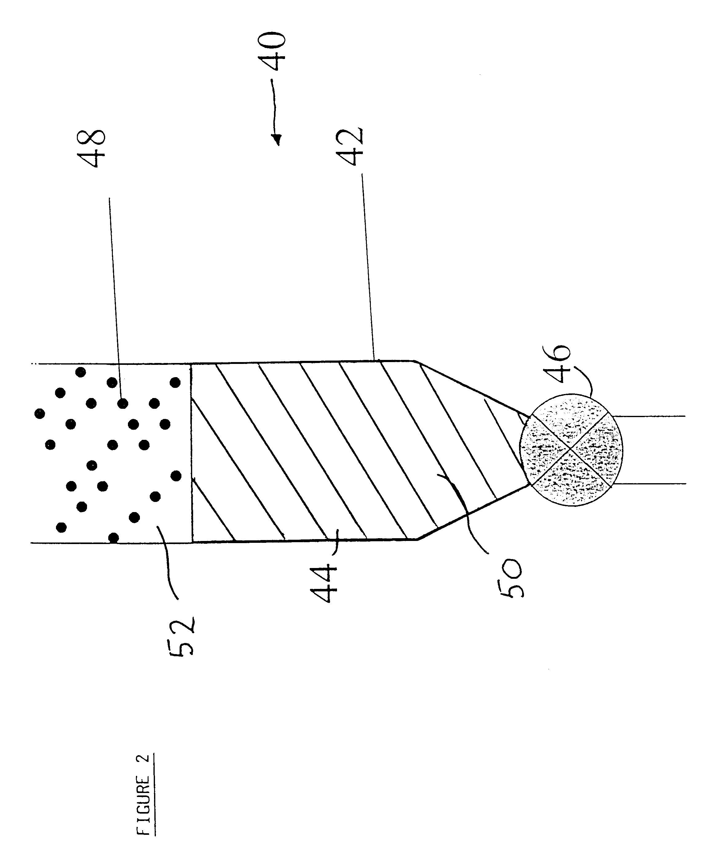
A process for producing polyolefins having a bimodal molecular weight distribution, the process comprising producing a first polyolefin fraction in the presence of a catalyst in a first loop reactor, and producing a second polyolefin fraction in the presence of the catalyst in a second loop reactor which is serially connected to and downstream of the first loop reactor, the first and second polyolefin fractions being blended in the second loop reactor to form a polyolefin having a bimodal molecular weight distribution, at least the first loop reactor containing a diluent under supercritical conditions which is circulated around the loop of the reactor, and wherein at least the first loop reactor is provided with a fluff concentrating device communicating with the loop and in which polyolefin fluff of the first fraction is concentrated in the supercritical diluent, and polyolefin fluff of the first polyolefin fraction is transferred together with an amount of supercritical diluent from the fluff concentrating device of the first loop reactor into the second loop reactor.

Description

BACKGROUND TO THE INVENTIONThe present invention relates to a process for the production of polyolefins, in particular polyethylene or polypropylene. In particular, the present invention relates to the production of a polyethylene having a multimodal molecular weight distribution, for example a bimodal molecular weight distribution.DESCRIPTION OF THE PRIOR ARTIt is known to produce polyethylene in liquid phase loop reactors in which ethylene monomer, and optionally an alpha-olefinic comonomer typically having from 3 to 10 carbon atoms, are circulated under pressure around a loop reactor by a circulation pump. The ethylene monomer and comonomer when present are present in a liquid diluent, such as an alkane, for example isobutane. Hydrogen may also be added to the reactor. A catalyst is also fed to the loop reactor. The catalyst for producing polyethylene may typically comprise a chromium-based catalyst, a Ziegler-Natta catalyst or a metallocene catalyst. The reactants in the diluent...

Claims


Application Information

Patent Timeline
Patent Type & Authority Patents(United States)
IPC IPC(8): B01J8/00B01J19/24C08F10/00C08F10/02C08F110/02C08F210/00C08F110/00C08F210/16C08F2/00C08F2/14C08F2/34
CPCB01J8/0005B01J8/005B01J8/0055B01J19/2435C08F10/02C08F2/14C08F2/01C08F2/06C08F2/001C08F210/16C08F110/02C08F2500/05C08F210/14Y02P20/582Y02P20/54
Inventor MARECHAL, PHILIPPE
Owner FINA RES SA
Learn More