Extended mount plate suspension for shock insensitivity

Inactive Publication Date: 2002-01-01
MAGNECOMP
View PDF1 Cites 3 Cited by
  • Summary
  • Abstract
  • Description
  • Claims
  • Application Information

AI Technical Summary

Benefits of technology

In the design of the present invention there is an extended mounting plate but the load beam length is kept to a total length of about 18 mm. The load beam is laminated by welding a part of the flexure thereto to increase stiffness. The mass center is moved closer to the slider. Hence, the moment developed due to the separation of the mass center and slider is smaller. The force propagated due to this moment through the load beam is smaller in value. This small value creates less traveling force and makes the vibration amplitude less.
2. Small traveling force creates less magnitude of excitation force in the beam and less amplitude of vibration.
5. As the pico slider is very small in size, shortening the load beam flying mass from 0.61 inch to 0.51 inch by having extended mount plate, results in 16% small load beam. The shorter load beam is more stable and its vibration amplitude gain is relatively small.
6. The wide body of the load beam makes the beam laterally stiff and hence improves sway and torsion modes.
7. The invention load beam longer vertical spring area allows more room to form optimized spring (to improve modes of vibrations and lower de-gramming) since stress due to bending is distributed over larger area.
In accordance with the invention, there is provided a substantially shock-insensitive disk drive suspension comprising a longitudinally extended load beam, a mounting plate for mounting the load beam to an actuator, the load beam having a base portion affixed to the mounting plate, a front portion of a predetermined width to which a flexure is attached, and a spring portion between the base portion and the front portion, the base portion being extended and the front portion shortened by the mounting plate having an extension at least 50% more in the load beam longitudinal direction as in the transverse direction, the flexure having substantially the predetermined width of the front portion and being laminated thereto, the load beam and the flexure having their respective centers of gravity spaced a distance 1, the distance 1 having a value minimizing the reaction moment Mr of the load beam when the load beam receives a shock force to thereby reduce the 2.sup.nd bending moment excitation of the load beam.

Problems solved by technology

A present challenge in the design of disk drive suspensions is increasing its ability to withstand high shock from the drive and at the same time not to damage the disk surface.

Method used


Image

  • Extended mount plate suspension for shock insensitivity
  • Extended mount plate suspension for shock insensitivity
  • Extended mount plate suspension for shock insensitivity

Examples


Embodiment Construction

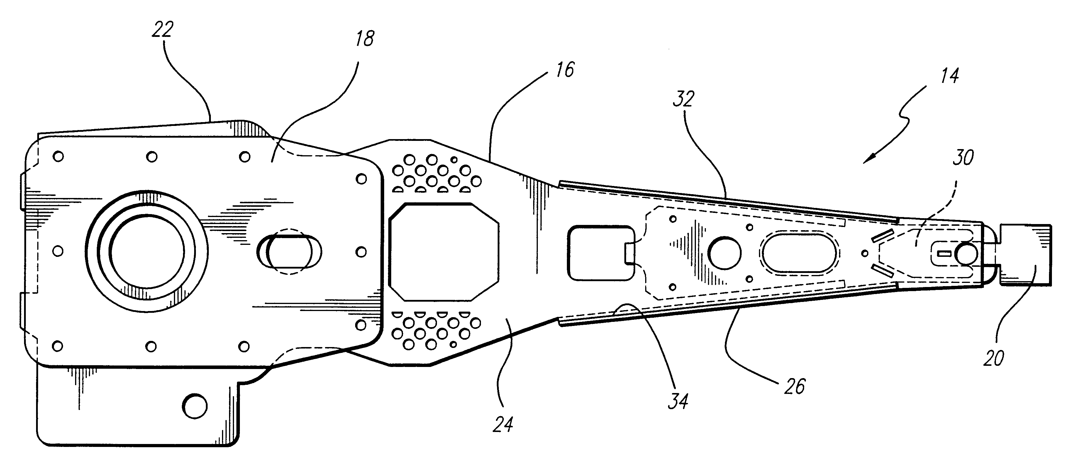
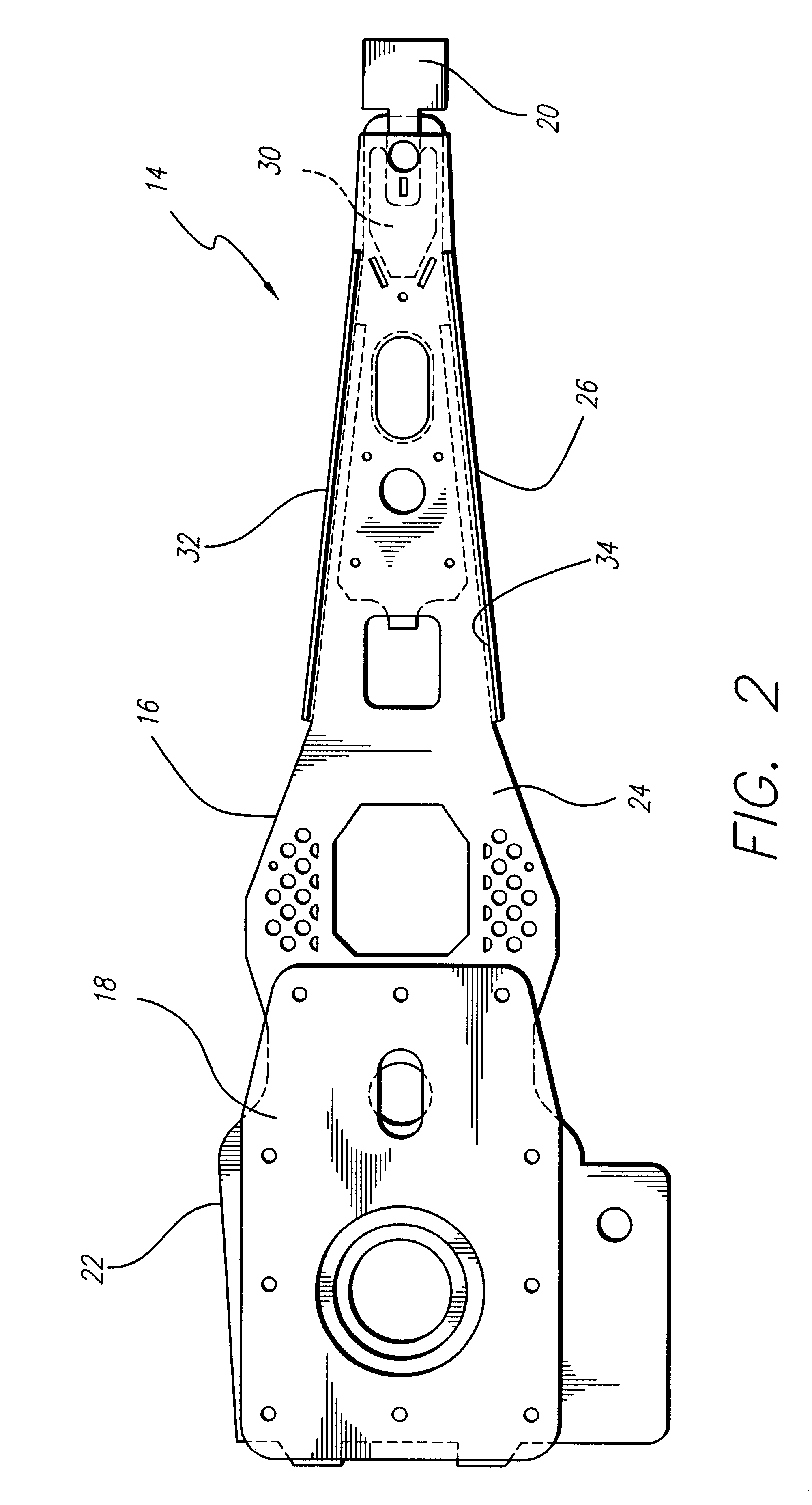
suspension generally configured as shown in FIG. 2 has the following dimensions:

L.sub.1 =0.279

L.sub.2 =0.1725

L.sub.3 =0.295

L.sub.4 =0.185.+-.0.003

Wherein:

L.sub.1 =Length of mount plate to front welds.

L.sub.2 =Length of spring section

L.sub.3 =Length of the load beam with rails.

L.sub.4 =Length of front welds from mount plate center.

Accordingly:

Total length, L.sub.T =(L.sub.1 +L.sub.2 +L.sub.3 =0.279+0.1725+0.295)=0.7465 inch

Ratio of mount plate length to total length:

L.sub.1 / L.sub.T =0.279 / 0.7465=0.374 or 37.4% of the total suspension length.

This ratio can range from 30 to 40%, .+-.10-15%, adjusting other ratios as necessary, providing the benefits of the invention are retained.

Ratio of spring section length to total length:

L.sub.2 / L.sub.T =0.1725 / 0.7465=0.231 or 23.1% of the total suspension.

This ratio can range from 20 to 25%, .+-.10-15%, adjusting other ratios as necessary, provided the benefit of strength distribution over a larger length than in a typical suspension is retained...


PUM

PropertyMeasurementUnit
lengthaaaaaaaaaa
sizeaaaaaaaaaa
massaaaaaaaaaa

Abstract

An improved disk drive suspension in which the load beam rail section is of reduced length, the base portion, defined by an extended mounting plate, increased in length, and the spring portion therebetween increased in length. The load beam rail section is laminated with a flexure substantially as wide as the rail section providing a very rigid structure. The centers of gravity of the load beam and flexure are closely approximate such that their reaction moment under shock is small, limiting the 2nd bending mode reaction of the load beam in favor of the 1st bending mode reaction, so that the slider carried by the load beam and flexure is kept flat to the disk against damaging the disk upon recontact.

Description

1. Technical FieldThis invention relates to suspensions for disk drives, and more particularly to suspensions useful in suspension-slider combinations. The invention suspensions are in comparison with previously known suspensions insensitive to shock. The suspensions have a lift-off acceleration characteristic of the suspension which is greatly increased over past suspensions, enabling improved shock performance and reduced likelihood of damage from shock and vibration events experienced by the disk drive. The invention suspension has especial utility with 30%-sized, or pico, sliders.2. Related ArtPico sliders having very little mass, and thus low inertia, tend readily to lift from a rest position on the disk surface during shock or vibration events in the disk drive. The preload imposed by the suspension in reaction to the movement of the slider forces the slider back against the disk possibly damaging the disk and / or the slider. The possibility of damage is particularly acute when...

Claims


Application Information

Patent Timeline
Patent Type & Authority Patents(United States)
IPC IPC(8): G11B5/48
CPCG11B5/4853G11B5/4806
Inventor KHAN, AMANULLAHIWAMOTO, ALEJANDRO KOJI
Owner MAGNECOMP
Why Eureka
Try Eureka