
Method for manufacturing an improved seal for fluid applications

a technology for fluid applications and manufacturing methods, applied in the direction of manufacturing tools, turning machine accessories, portability lathes, etc., can solve the problems of sealing failure, high cost, and high cost, and achieve the effect of better withstand

Inactive Publication Date: 2001-12-11
ADVANCED METAL PROD INC
View PDF8 Cites 10 Cited by
  • Summary
  • Abstract
  • Description
  • Claims
  • Application Information

AI Technical Summary

Benefits of technology

It is an object of the present invention to provide an improved method of creating a seal for use in fluid applications that better withstands the forces to which it is subjected.
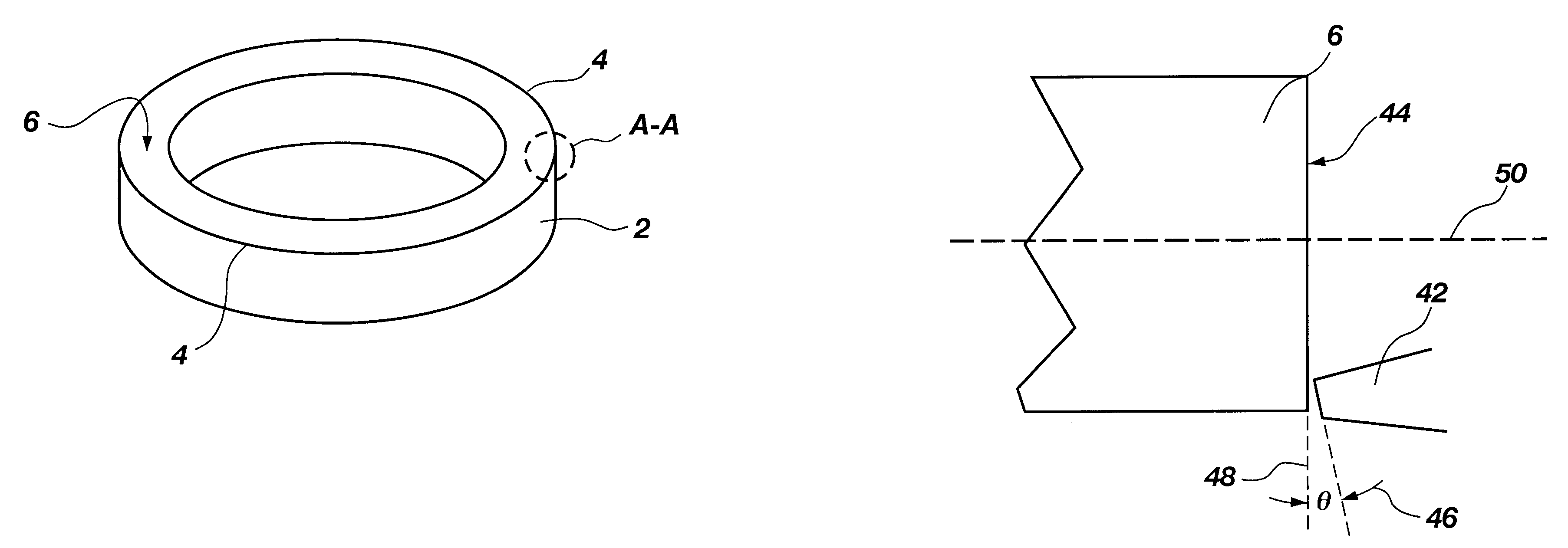
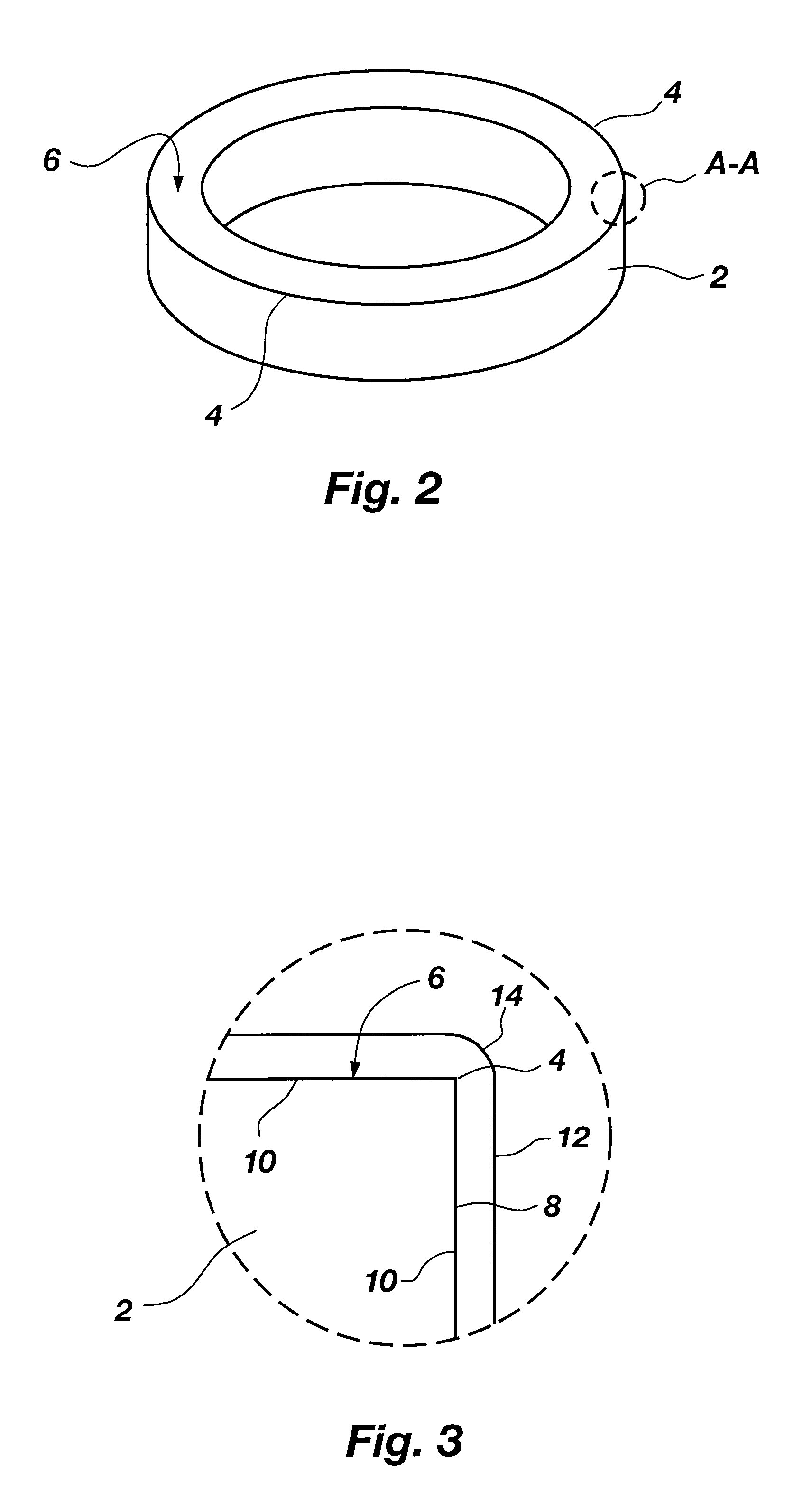
FIG. 4 is a close-up and cross-sectional view of a portion of the annular mechanical seal which shows that a portion along the outer edge is formed into a chamfer in order to prevent chip formation along the outer edge during the turning process.

Problems solved by technology

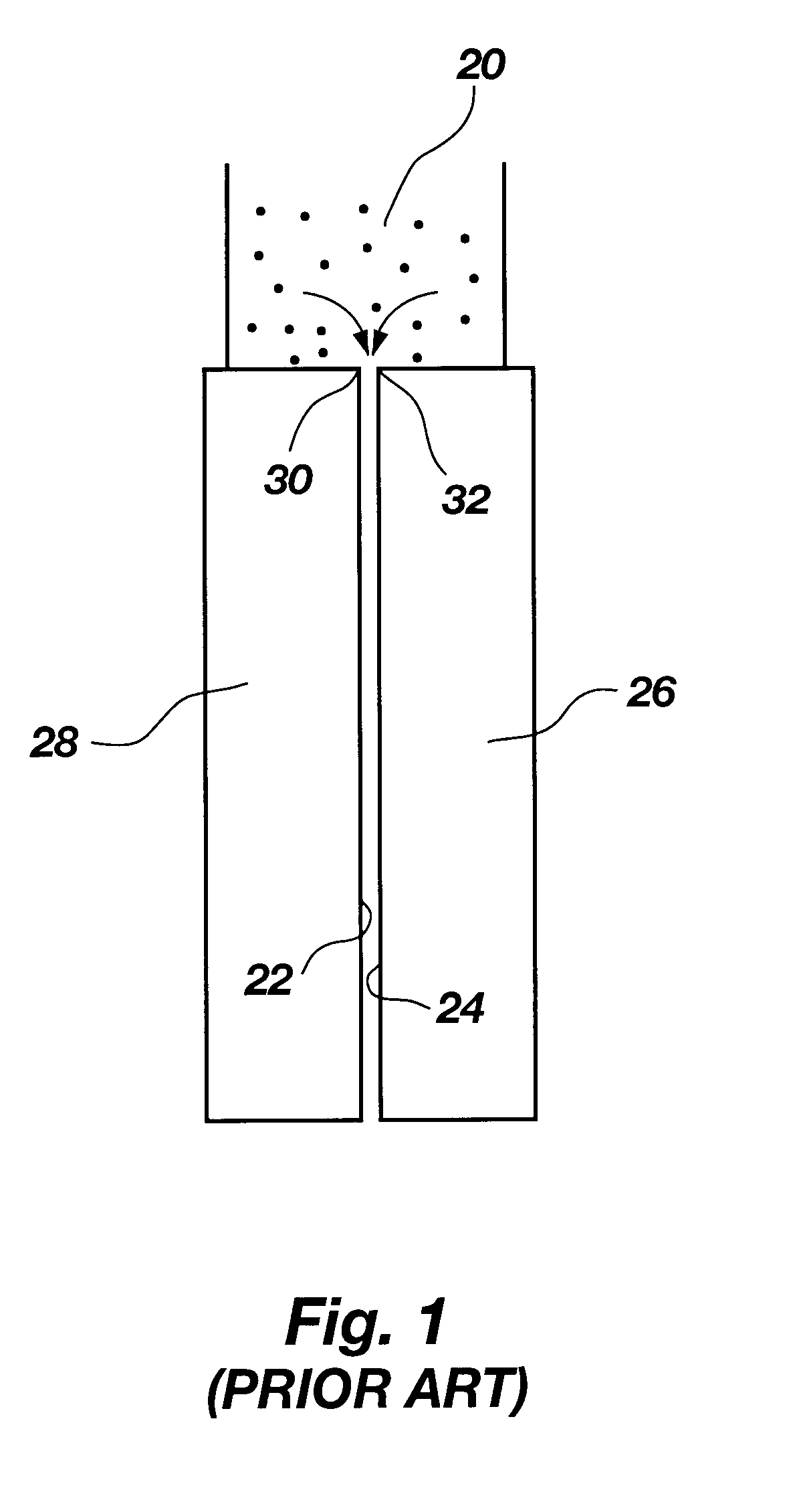
One result of this rigidity is that seal assemblies are very compact.
Another problem that a seal face must contend with is that of corrosion.
When corrosion attacks the seal face, it causes pitting, leaching, etc., which can lead to seal failure.
Disadvantageously, ceramics are also extremely brittle, less able to withstand thermal and mechanical shock, and require special handling.
Other limiting factors when choosing cemented tungsten carbide as a seal material are size, complexity, and cost.
However, because of the shrinkage, the sintered blanks must have carbide stock which is generally removed by grinding for the part to achieve its finished size.
If more than 0.002" stock is removed per pass with a grinding wheel, the risk of surface cracking and heat checking increases dramatically.
For example, grinding leaves surface damage and residual surface stresses.
Therefore, feeds of the seals are relatively slow and grinding depths are limited.
Furthermore, inside diameters of the seals take longer to grind because the wheel is smaller and grinds at a slower surface speed.
Because stock is removed by a grinding wheel, finished part geometries can only be as complex as a grinding wheel geometry will allow.
Disadvantageously, cemented tungsten carbide rings (such as those used to form large seals) often warp from the residual grinding stresses and require that the part be scrapped or reworked at additional cost.

Method used


Image

  • Method for manufacturing an improved seal for fluid applications
  • Method for manufacturing an improved seal for fluid applications
  • Method for manufacturing an improved seal for fluid applications

Examples


Embodiment Construction

Reference will now be made to the invention in which the various elements of the present invention will be given numerical designations and in which the invention will be discussed so as to enable one skilled in the art to make and use the invention. It is to be understood that the following description is only exemplary of the principles of the present invention, and should not be viewed as narrowing the claims which follow.

The presently preferred embodiment of the present invention comprises utilizing a turning process to manufacture a mechanical seal from cemented tungsten carbide. As explained previously, a sintered blank is often preferred as the material for a mechanical seal because of its hardness. Furthermore, those skilled in the art of using cemented tungsten carbide for mechanical seals grind them. This is because of a mind set which is common among those in the industry.

Specifically, carbide is generally not considered "turnable" on a lathe because it is known that carb...


PUM

PropertyMeasurementUnit
Angleaaaaaaaaaa
Angleaaaaaaaaaa
Angleaaaaaaaaaa

Abstract

A method for manufacturing a mechanical seal used in fluid applications, wherein the mechanical seal is comprised of a sintered (cemented) tungsten carbide ring that is turned on a lathe at a negative top rake angle instead of formed by grinding. The cemented tungsten carbide ring is initially prepared by rounding corners of the top surface to form a radii. The resulting mechanical seal yields significantly less surface damage, can be formed using faster cutting speeds and feeds than when grinding, enables formation of a greater range of complex geometries for the mechanical seals, and requires fewer passes than grinding. The compact is also formed at a significantly reduced cost as compared to grinding.

Description

1. Field of the InventionThis invention pertains generally to a method and apparatus for manufacturing a mechanical seal for use in sealing liquids in fluid handling applications. More specifically, seal faces are manufactured in such a way that they have improved properties of flatness, resistance to deformation, etc.2. State of the ArtMechanical seals are used to seal liquids in fluid handling applications. The seals are manufactured from a variety of metals and ceramic materials. One of the most versatile and therefore the most common material used in seal assemblies is cemented tungsten carbide.One of the most common applications of mechanical seals is for sealing shafts on pumps where it is desirable to prevent the passage of a fluid past the shaft. It is also the case that the many types of pumps and media (fluid) being pumped require a large range of sizes and types of seals. Accordingly, seal faces typically range in diameter from less than an inch to greater than eighteen i...

Claims


Application Information

Patent Timeline
IPC IPC(8): B23B1/00
CPCB23B1/00B23B2222/28B23B2226/31Y10T82/16Y10T82/10Y10T82/23Y10T82/2512B23B2260/126
Inventor FELTER, PAUL ALLENNYE, TRACY SHANE
Owner ADVANCED METAL PROD INC
Learn More