
Liquid crystal display cell

a display cell and liquid crystal technology, applied in static indicating devices, instruments, non-linear optics, etc., can solve problems such as shifting or drifting of disclination lines, deteriorating display cell performance,

Inactive Publication Date: 2001-11-27
NEC CORP
View PDF33 Cites 27 Cited by
  • Summary
  • Abstract
  • Description
  • Claims
  • Application Information

AI Technical Summary

Problems solved by technology

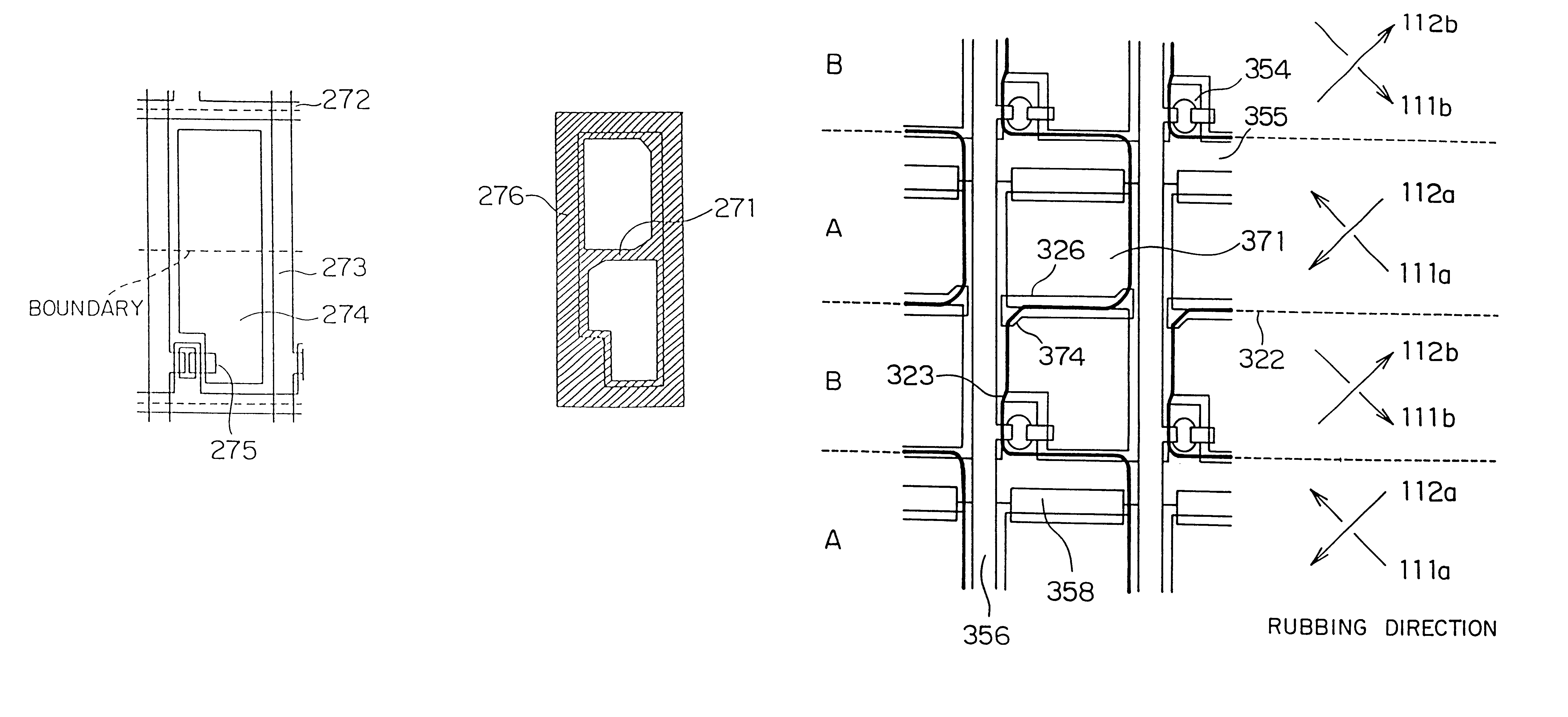
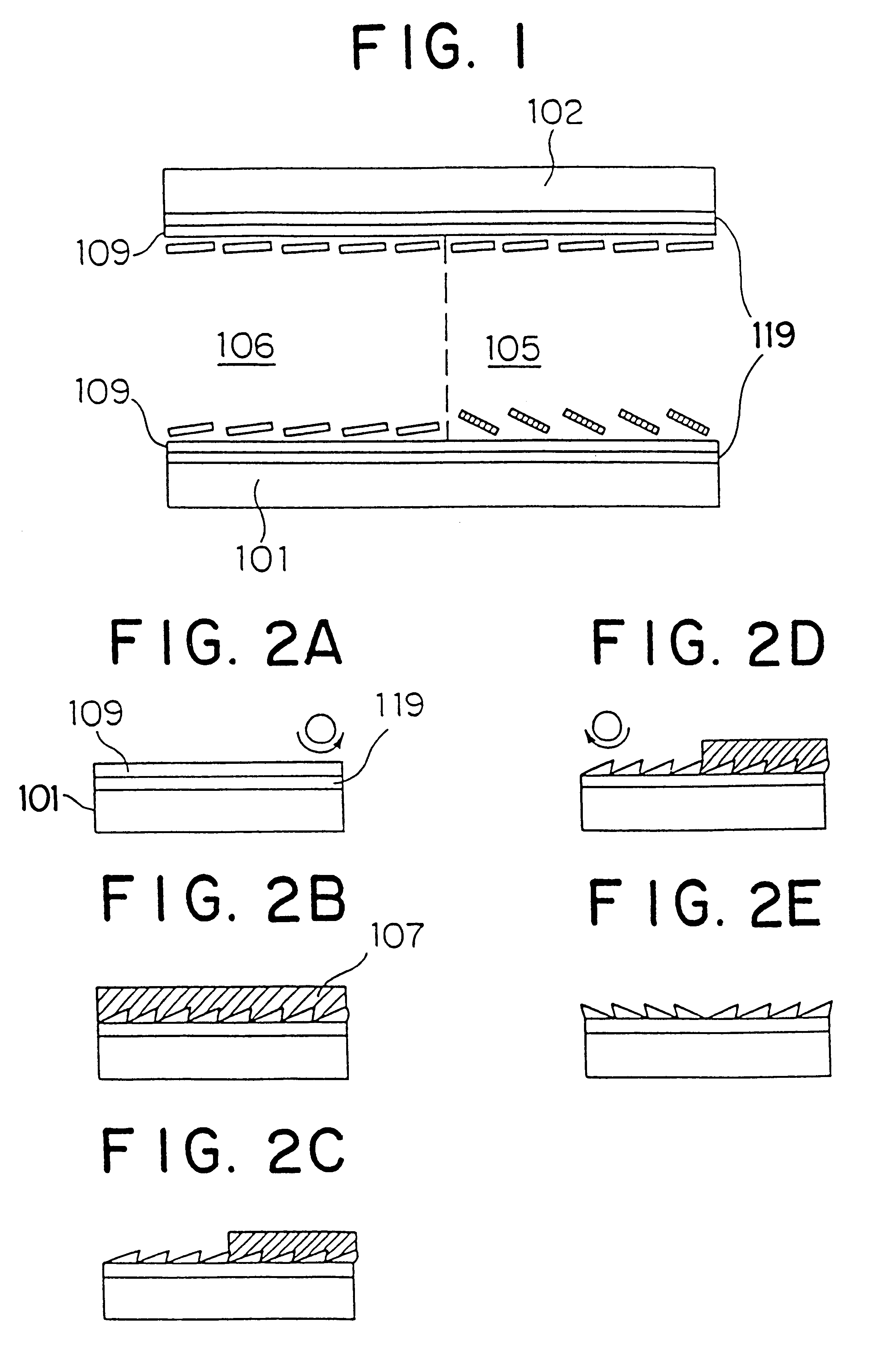
The conventional orientation alignments for dividing a pixel as described above have problems that one orientation direction turns dominant over the other, depending on combination of rubbing orientations between the two areas.
The shift of the disclination line is observed as an afterimage, which deteriorates performance of display cells.
On the contrary, if the pre-tilt angle in the second domain exhibiting an ordinary TN deformation is set larger than the pre-tilt angle in the first domain exhibiting a splay-type TN deformation in the vicinity of the substrate, the disclination line is not fixed well, resulting in shifting or drifting of the disclination line due to existence of a lateral electric field during operation of the liquid crystal display cell.

Method used


Image

  • Liquid crystal display cell
  • Liquid crystal display cell
  • Liquid crystal display cell

Examples


embodiment 2

A liquid crystal display cell according to Embodiment 2 was fabricated similarly to Embodiment 1 except that the orientation film providing the lower pre-tilt angle for the counter substrate 202 in Embodiment 1 was replaced by an orientation film made of polyimide called RN-1006 and supplied from Nissan Chemical Corp. The evaluation procedure confirmed that Embodiment 2 exhibited excellent characteristics provided by the two-orientation alignment. Further, the crystal rotation technology evaluated the pre-tilt angle provided by the polyimide made of RN-1006 as 3 degrees in an anti-parallel cell fabricated for Embodiment 2 similarly to Embodiment 1.

embodiment 3

A liquid crystal cell according to Embodiment 3 was fabricated similarly to Embodiment 1, except the orientation film providing the high pre-tilt angle and the baking temperature were replaced by an orientation film made of a polyimide raw resin called RN-715 supplied from Nissan Chemical Corp. and 250.degree. C., respectively. The results verified an excellent characteristic resulting from a divided orientation alignment configuration. The pre-tilt angle provided by the RN-715 film was evaluated by using crystal rotation technology similarly to Embodiment 1. The results showed that the first portions covered with the photoresist pattern during the second rubbing step provided a pre-tilt angle of 12 degrees while the second portions exposed directly to the second rubbing step provided a pre-tilt angle of 9 degrees.

embodiment 4

A liquid crystal cell according to Embodiment 4 was fabricated similarly to Embodiment 1, except the orientation film providing the high pre-tilt angle and the baking emperature in Embodiment 1 were replaced by an orientation film made of a polyimide raw resin called LC-102 supplied from Hitachi Chemical Corp. and 250.degree. C., respectively. The results showed an excellent characteristic resulting from a divided orientation alignment configuration. The pre-tilt angle provided by LC-102 was measured by a crystal rotation technology similarly to Embodiment 1. The results showed that the first portions covered with the photoresist pattern during the second rubbing step provided a pre-tilt angle of 3 degrees while the second portions exposed directly to the second rubbing step provided a pre-tilt angle of 2 degrees.


PUM

PropertyMeasurementUnit
pre-tilt angleaaaaaaaaaa

Abstract

Liquid crystal display (LCD) has sub-pixel domains in each of pixels to obtain a wide viewing angle. The sub-pixel domains are formed by divided orientation alignment in which the sub-pixel domain are subjected to rubbing in different directions opposite to each other. The liquid crystal has a splay-type TN deformation structure in the first sub-pixel domain and a normal TN deformation structure in the second sub-pixel domain. The pre-tilt angles of the liquid crystal in the first domain and second domain are selected to obtain a wide viewing angle. The LCD has a shield pattern for for shielding disclination causing afterimages and storage capacitor electrodes having a function as a signal lines.

Description

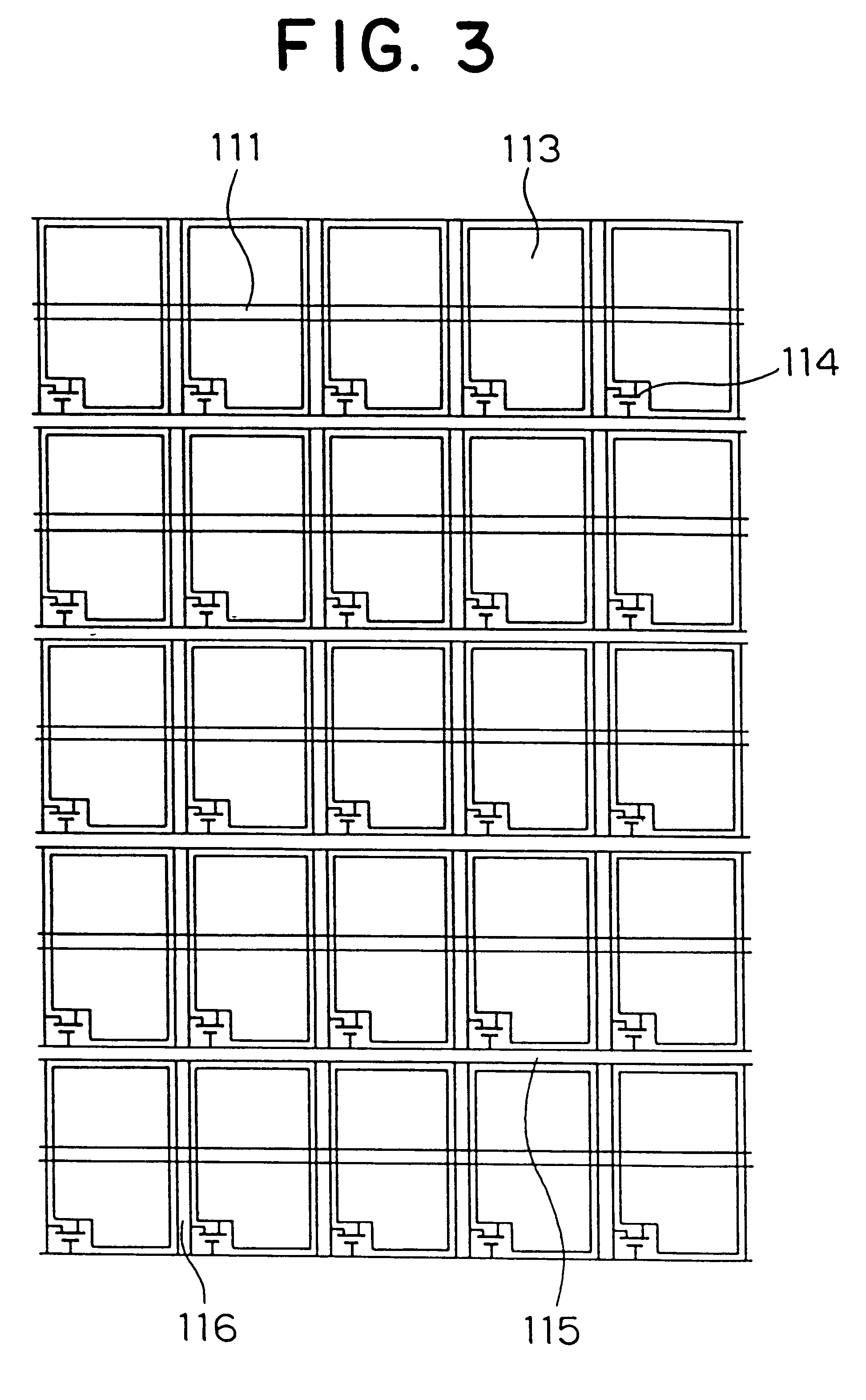
1. Field of the InventionThe present invention relates to a liquid crystal display (LCD) cell and, more particularly, to an LCD cell having a wider view angle for display by providing a plurality of active areas on a substrate.2. Description of the Related ArtLiquid crystal display cells having a plurality of minute areas in each pixel, which is generally called sub-pixel domains, have been reported in Patent Publication Nos. JP-A-82-186735, JP-B-83-43723, JP-A-84-211019, JP-A-88-106624, JP-A-89-88520, JP-A-89-245223, JP-A-93-173138, JP-A-93-203951. The main object in dividing a pixel into a plurality of minute areas is to align orientations of the respective areas so that viewing angle of the areas constituting one pixel may be compensated by each other in the pixel. There exist two major technologies for aligning the orientation of a liquid crystal. One is a slanting deposition technology of an oxidized silicon film while the other is a rubbing technology in which a polyimide film...

Claims


Application Information

Patent Timeline
Patent Type & Authority Patents(United States)
IPC IPC(8): G02F1/1333G02F1/13G02F1/1337G02F1/1335G02F1/1343G02F1/1362
CPCG02F1/133753G02F1/133512G02F1/133707G02F1/136213G02F2001/133757G02F2001/133761G02F1/133757G02F1/133761G02F1/133784
Inventor SUZUKI, MASAYOSHITAKATORI, KEN-ICHISUMIYOSHI, KENKANEKO, SETSUOSUZUKI, TERUAKISHIBAHARA, HIDEOHIRAI, YOSHIHIKO
Owner NEC CORP
Learn More