
Joined metal member and method of joining said member

Inactive Publication Date: 2001-11-27
MAZDA MOTOR CORP
View PDF9 Cites 33 Cited by
  • Summary
  • Abstract
  • Description
  • Claims
  • Application Information

AI Technical Summary

Benefits of technology

With this scheme, although the first metal member includes pores therein unlike an infiltrated material which is infiltrated with Cu or the like, the first metal member is sintered with the particles having high electrical conductivity dispersed therein beforehand and, therefore, resistivity of the bulk of the first metal member can be maintained at a somewhat high level comparable to that of the infiltrated material. This makes it possible to inhibit the heat generation when passing a current, despite the presence of the pores, and achieve a better joint without the need for infiltrating the material with Cu or the like after sintering.
Since the plastic flow effectively destroys the oxide film formed on the second metal member surface, it is not necessary to protect the surface of the second metal member. It is also made possible to cause the plastic flow of the second metal member easily by the pressure applied to hold the first and second metal members together, and therefore no special means is required for the plastic flow. In the present inventions, in particular, since the oxide film and contaminants are removed from the surface of the second metal member together with the residually molten brazing material, the brazing material can be surely diffused into the second metal member, thereby forming the diffusion layer of the brazing material and the second metal member surely by a simple method. Thus further improvement can be achieved in the joint strength of the joined metal member.

Problems solved by technology

However, impregnation of an infiltrating metal into the sintered material requires an additional step in the process, which leads to increased production cost.
Also, because the infiltrating metal generally increases the thermal conductivity, a valve seat or the like to be used at a high temperature suffers such a problem that the heat dissipation efficiency becomes too high due to the combined effects of both the increased thermal conductivity and the joining effect, thus making it difficult to form an oxide film on the surface, which may lead to poor wear resistance on the valve sheet.
As a result, the first metal member is likely to be overheated due to the low thermal conductivity.
Moreover, since the first metal member has relatively lower strength due to porosity, the surface to be joined of the first metal member is likely to deform.
However, this causes the valve seat 3 to be cooled down rapidly from the temperature above the transformation point to cause hardening of the central portion in the vertical direction, thus resulting in increased hardness.
On the other hand, there is such a problem that cracks are likely to develop in the wall, particularly in corners, of the combustion chamber 42a of the piston 42.
But this method has such a problem that cycle time of casting becomes longer resulting in a low productivity.
As a consequence, sufficient plastic flow of the joining surface 2a of the cylinder head body 2 cannot be achieved, making it impossible to achieve sufficient effect of destroying the oxide film.

Method used


Image

  • Joined metal member and method of joining said member
  • Joined metal member and method of joining said member
  • Joined metal member and method of joining said member

Examples


embodiment 5

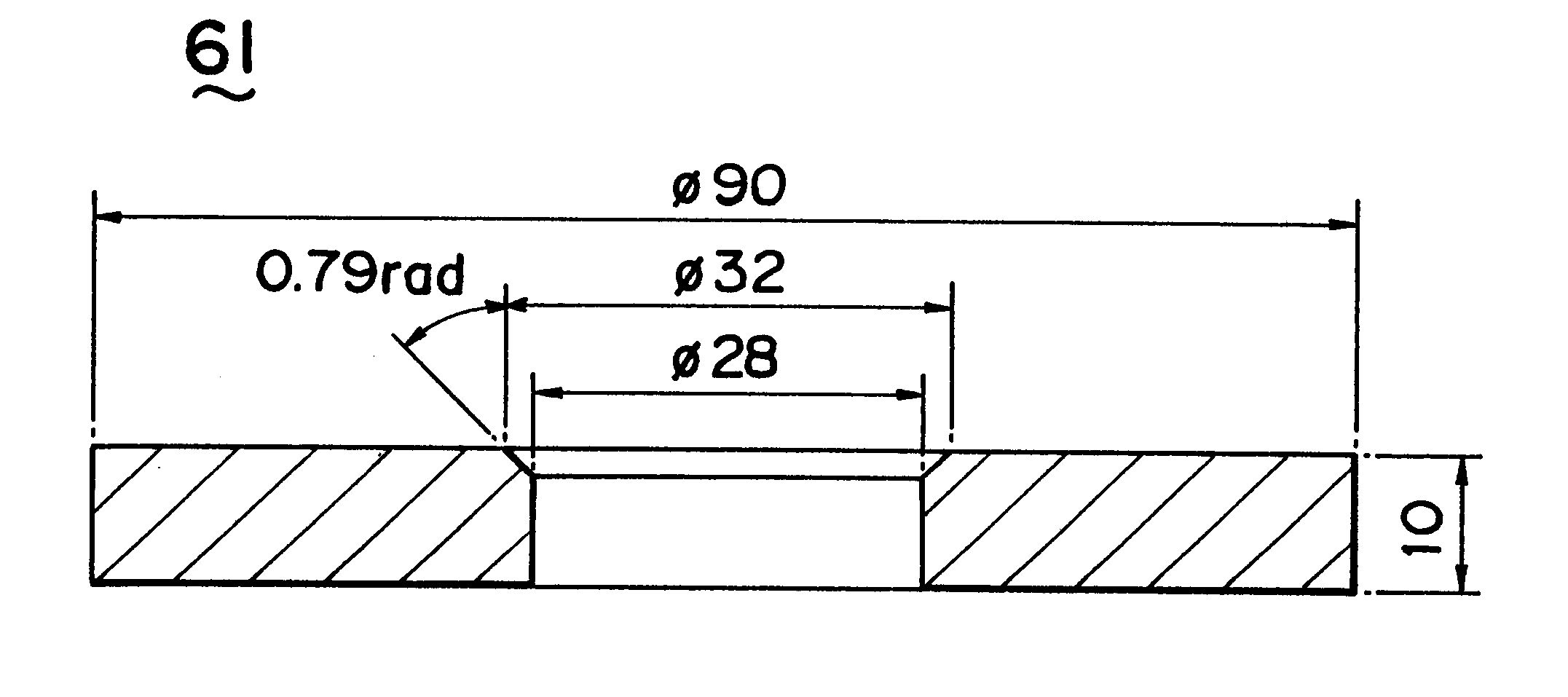
FIG. 36 shows a microphotograph (magnified about 10,000 times) of the joining surfaces of the valve seat and the test piece 61 after joining in The valve seat (including the portion appearing white) is shown on the left-hand side and the test piece 61 on the right-hand side in this photograph. The diffusion-joined layer and the molten reaction layer are shown in the gray portion in-between. It can be seen that both layers are about 1 .mu.m thick. Element analysis showed that these layers included Fe, Zn and Al.

Effect of the pressure was studied more closely as follows. The valve seat was joined to the test piece 61 with pressures of 9807 N (1000 kgf), 14710 N (1500 kgf) and 29420 N (3000 kgf) while the method of coating with the brazing material, seat shape and the taper angle .theta.1 were set similarly to Basic Examples 4, 5. Then the knock-off load was measured similarly to the first knock-off load measuring test.

Hardness was measured on the test pieces 61 subjected to the press...


PUM

PropertyMeasurementUnit
Fractionaaaaaaaaaa
Fractionaaaaaaaaaa
Fractionaaaaaaaaaa

Abstract

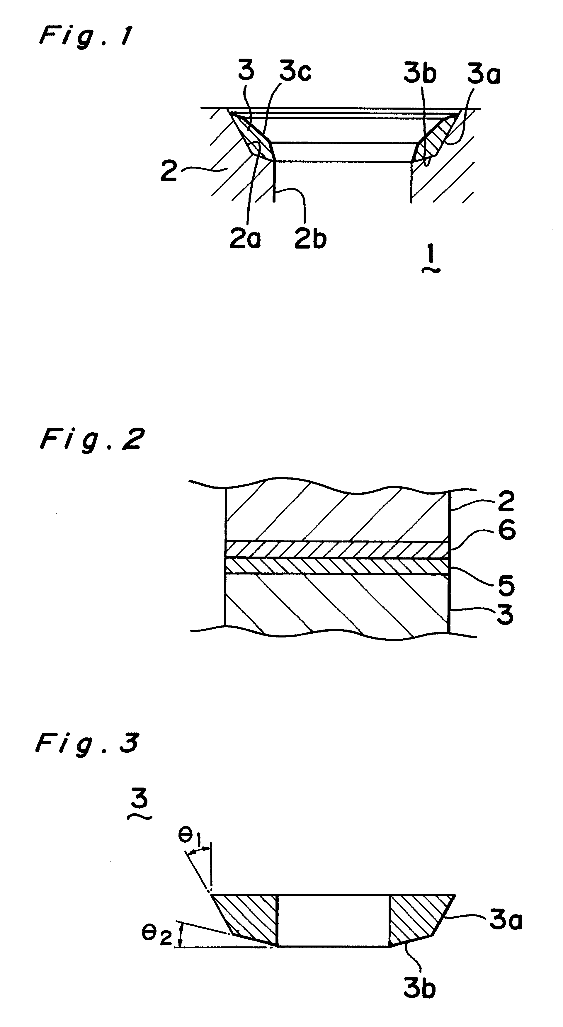
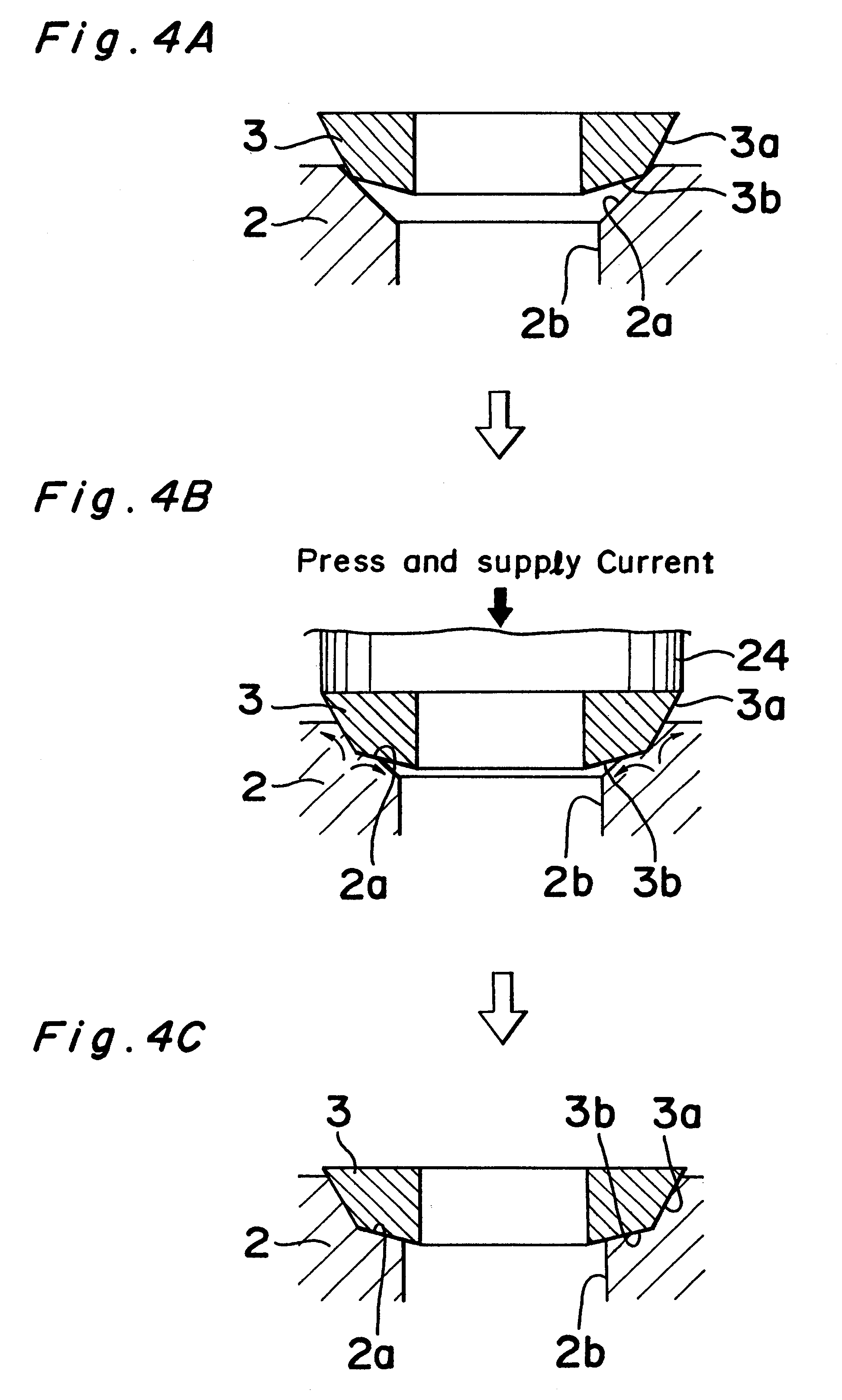
In order to provide a method of joining a cylinder head 2 and a valve seat 3 by press and heat generated on passing an electrical current through both members 2, 3, to achieve satisfactory joining with minimized heat generated inside when the current is supplied, while eliminating the need for an infiltration step and reduce the production cost, inhibiting an increase in thermal conductivity of the valve seat 3 and improving the wear resistance thereof. The valve seat 3 is made of a sintered material made from a powdery material with a high electrical conductivity element such as Cu dispersed therein. The current and the pressure are applied with a first joining surface 3a of the valve seat 3 and a joining surface 2a of the cylinder head body 2 being put into surface contact with each other in advance.

Description

BACKGROUND OF THE PRESENT INVENTION1. Field of the InventionThe present invention relates to a joined metal member comprising two metal members joined with each other by press and heat generated on passing an electrical current through the metal members, and a method of joining said member.2. Prior ArtVarious methods are known for joining metal members in such cases as joining a valve seat of an engine cylinder head onto the periphery of an opening of air intake or exhaust port of the cylinder head body.For example, Japanese Patent Publication JP-A 8-100701 discloses a method of joining a valve seat with an Al-based cylinder head body by brazing using an Al--Zn brazing material and a fluoride flux.Also such a method is known as disclosed in Japanese Patent Publication JP-A 58-13481, where metal members are joined by resistance welding which utilizes the heat generated by contact resistance between mating surfaces of the two members. With regard to the resistance welding, it has been...

Claims


Application Information

Patent Timeline
IPC IPC(8): B23K1/19B23K20/16B23K20/227B23K20/22F01L3/02B23K11/00B23K1/20B23K11/20B23K11/34B23K20/00B23K103/20F01L3/22F02F1/24
CPCB23K1/19B23K20/16B23K20/2275F01L3/02F02F1/24
Inventor NOMURA, SEIJINANBA, SATOSHI
Owner MAZDA MOTOR CORP
Learn More