
Die collet for a semiconductor chip and apparatus for bonding semiconductor chip to a lead frame

Inactive Publication Date: 2001-11-27
SAMSUNG ELECTRONICS CO LTD
View PDF15 Cites 26 Cited by
  • Summary
  • Abstract
  • Description
  • Claims
  • Application Information

AI Technical Summary

Problems solved by technology

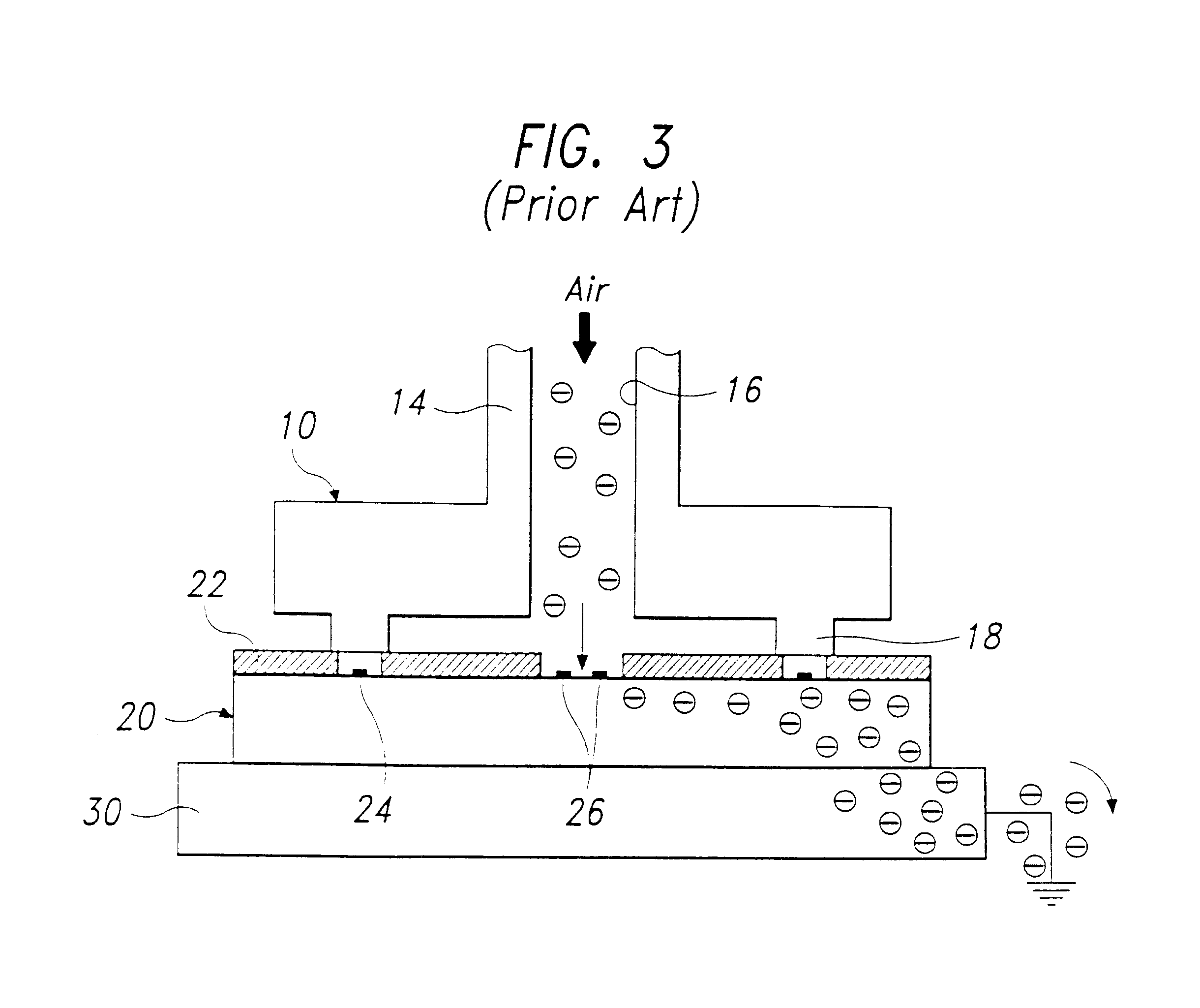
During the manufacture of semiconductor devices, the equipment or operator often produces an electrostatic discharge (ESD), and the electrostatic discharge can damage semiconductor chip 20 by causing a breakdown of the insulation or breakdown of integrated circuits.
Damage to semiconductor chips from electrostatic discharge is likely to become a more serious problem in light of the continuing trend to higher circuit integration and narrower pattern width.
However, this approach requires high level of cleanness in the electrical die sorting and consequently additional manufacturing costs.
However, this approach also increases the manufacturing cost.

Method used


Image

  • Die collet for a semiconductor chip and apparatus for bonding semiconductor chip to a lead frame
  • Die collet for a semiconductor chip and apparatus for bonding semiconductor chip to a lead frame
  • Die collet for a semiconductor chip and apparatus for bonding semiconductor chip to a lead frame

Examples


first embodiment

die bonding apparatus according to the present invention is depicted in FIG. 8. Die attaching apparatus 100 has two pickup tools 110 and 130. A first pickup tool 110 picks up semiconductor chip 20 from sawed wafer 50 and then puts semiconductor chip 20 on an aligning stage 120. Then, an optical instrument 122 such as a camera detects a misalignment of semiconductor chip 20. Based on the information from optical instrument 122, aligning stage 120 moves rotationally and along X-Y axis to align semiconductor chip 20 correctly. After the alignment is done, a second pickup tool 130 picks up aligned semiconductor chip 20 and places semiconductor chip 20 on a die pad 62 of a lead frame 60. The attaching apparatus except for two pickup tools 110 and 130 described in the embodiment in FIG. 8 are available in conventional die bonders such as Model PA100 from Shinkawa Company in Japan, and Model AT3000 Series from Hitachi Tokyo Electron Company in Japan.

Before placing semiconductor chip 20 on ...

second embodiment

die bonding apparatus according to the present invention is depicted in FIG. 9. A die attaching apparatus 200 in FIG. 9 has a single pickup tool 210. Pickup tool 210 of this apparatus performs the same function as pickup tool 110 in FIG. 8, namely, transferring semiconductor chip 20 from sawed wafer 50 to aligning stage 220. However, there are some differences between two apparatuses in FIGS. 8 and 9 in a process after the die alignment.

Apparatus 200 of FIG. 9 employs aligning stage 220 which moves to a lead frame 70. That is, after receiving and aligning semiconductor chip 20 like aligning stage 120 in FIG. 8, aligning stage 220 moves and stops under lead frame 70. Then, a bond head 230 pushes lead frame 70 down, and at the same time, aligning stage 220 moves upward to create a bond between semiconductor chip 20 and lead frame 70. In this case, generally, adhesive has been already applied to the bonded surface of lead frame 70. The die attaching apparatus except for pickup tool 210...


PUM

PropertyMeasurementUnit
Structureaaaaaaaaaa
Vacuumaaaaaaaaaa

Abstract

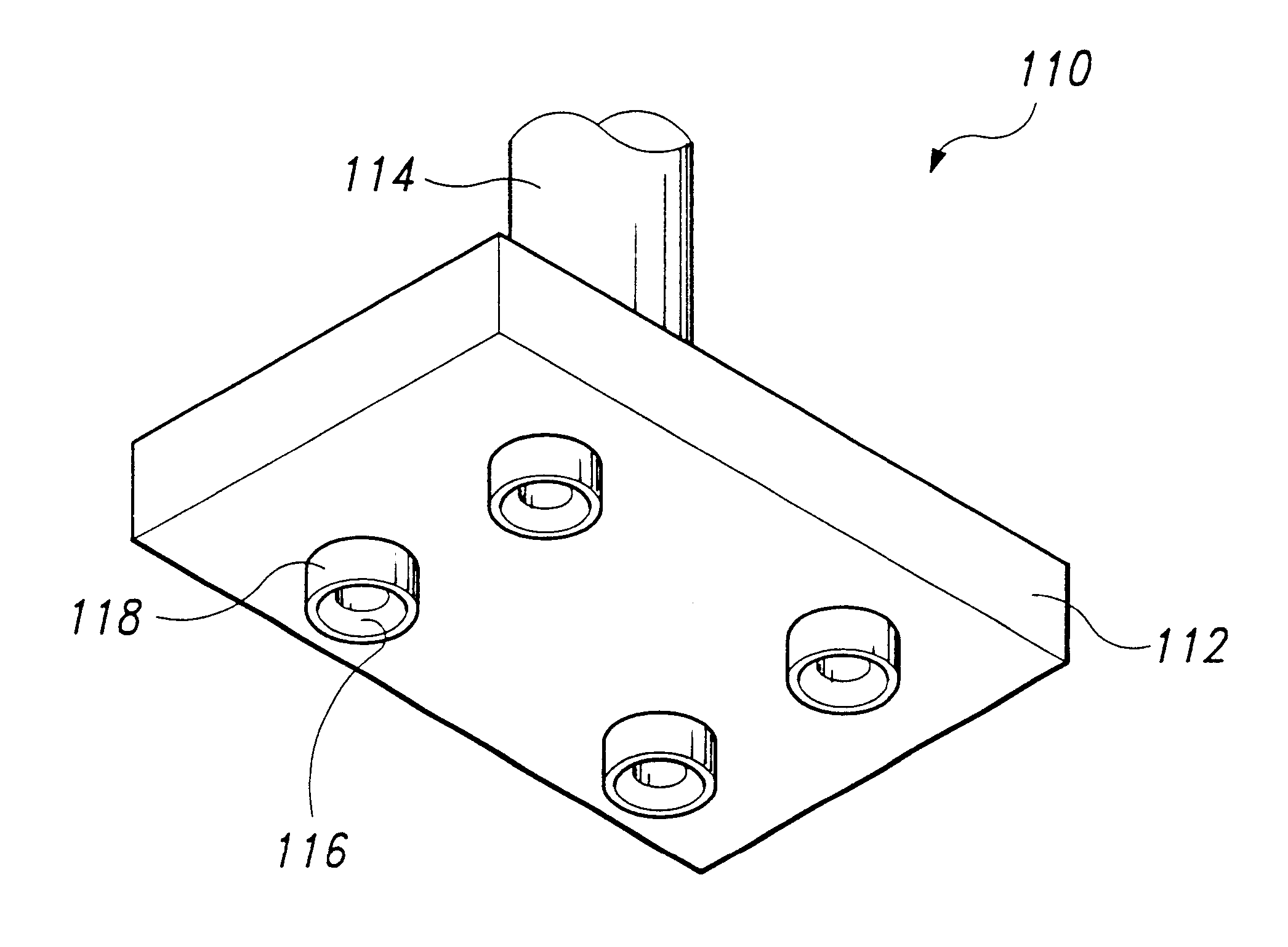
A die collet for a semiconductor chip having an exposed electrical structure, the die collet including a body having a vacuum line connected thereto, the die collet including a plurality of parts each having a vacuum hole communicating with the vacuum line. Apparatus for bonding a semiconductor chip to a lead frame, the apparatus including a first die collet for picking up the semiconductor chip, on aligning stage for receiving the semiconductor chip from the first pickup tool and aligning the semiconductor chip. A second die collet picks up the semiconductor chip from the aligning stage and places the semiconductor chip on a lead frame. The first and second die collets are constructed as described above.

Description

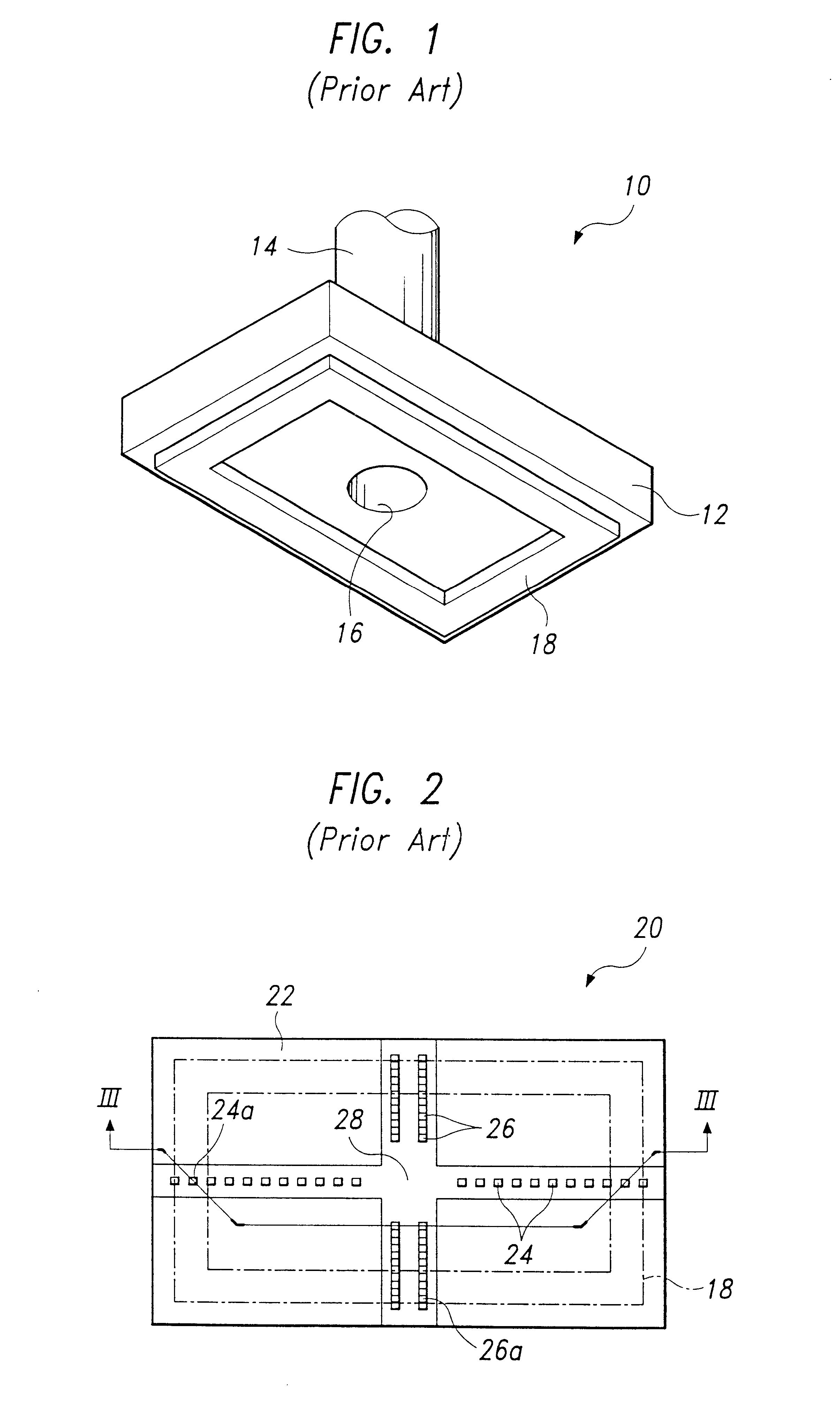
1. Field of the InventionThe present invention relates to an apparatus for manufacturing semiconductor integrated circuit devices, and more specifically to a semiconductor die bonding apparatus having a die pickup tool with multiple contact parts for preventing electrostatic discharge from damaging the semiconductor integrated circuit devices during the manufacturing process.2. Description of the Prior ArtIn manufacturing semiconductor integrated circuit (IC) devices, a semiconductor wafer which includes a number of semiconductor chips is produced. Then, the assembly of the semiconductor chips starts with a sawing step which separates the semiconductor wafer into individual semiconductor chips. After the sawing, a die bonding step bonds the semiconductor chips to a lead frame. A die bonding apparatus picks up the semiconductor chips by using a tool which is commonly called a pickup collet, a transfer collet or a bond collet.FIG. 1 shows a conventional pickup collet 10. As shown in F...

Claims


Application Information

Patent Timeline
IPC IPC(8): H01L21/683H01L21/67H01L21/00H05K13/04H01L21/52H01L21/687
CPCH01L21/67144H01L21/6838H05K13/0408Y10T29/53191H01L2924/0002H01L2924/00H05K13/0409H01L21/687
Inventor JIN, HO TAECHOI, HEE KOOK
Owner SAMSUNG ELECTRONICS CO LTD
Learn More