Evaporative emission control system for internal combustion engine

Inactive Publication Date: 2001-10-23
HONDA MOTOR CO LTD
View PDF8 Cites 30 Cited by
  • Summary
  • Abstract
  • Description
  • Claims
  • Application Information

AI Technical Summary

Benefits of technology

It is accordingly an object of the present invention to provide an evaporative emission control system which can properly control the ratio between the tank purge amount and the canister purge amount to realize quick pressure reduction in the fuel tank and ensuring the storage capacity of the canister in a well balanced manner.
With this configuration, the first and second control means are controlled according to the result of comparison between the target pressure and the detected pressure in the fuel tank. Accordingly, when the detected pressure in the fuel tank is in the vicinity of the atmospheric pressure and much higher than the target pressure, tank purge through the first control valve is preferentially carried out. Conversely, when the detected pressure in the fuel tank is near the target pressure, canister purge through the second control valve is preferentially carried out. Accordingly, quick pressure reduction in the fuel tank and ensuring the storage capacity of the canister can be realized in a well balanced manner.
Preferably, the third control means controls the first and second control means so that the amount of evaporative fuel to be purged through the first evaporative fuel passage is decreased and the amount of evaporative fuel to be purged through the second evaporative fuel passage is increased with a decrease in the detected pressure toward the target pressure.
Accordingly, it is possible to prevent the deviation of an air-fuel ratio from a target value due to the execution of the tank purge in which an evaporative fuel amount is large, and it is also possible to increase the maximum of a total purge amount as the sum of the tank purge amount and the canister purge amount, thereby allowing quicker pressure reduction in the fuel tank and quicker canister purge.

Problems solved by technology

As a result, the tank purge amount is relatively small, causing a delay of pressure reduction in the fuel tank.
Conversely, in the case of adopting a method of preferentially determining the tank purge amount, there occurs another problem that the canister purge amount becomes lacking to cause a reduction in storage capacity of the canister (especially, the storage capacity required in refueling).

Method used


Image

  • Evaporative emission control system for internal combustion engine
  • Evaporative emission control system for internal combustion engine
  • Evaporative emission control system for internal combustion engine

Examples


Embodiment Construction

A preferred embodiment of the present invention will now be described with reference to the drawings.

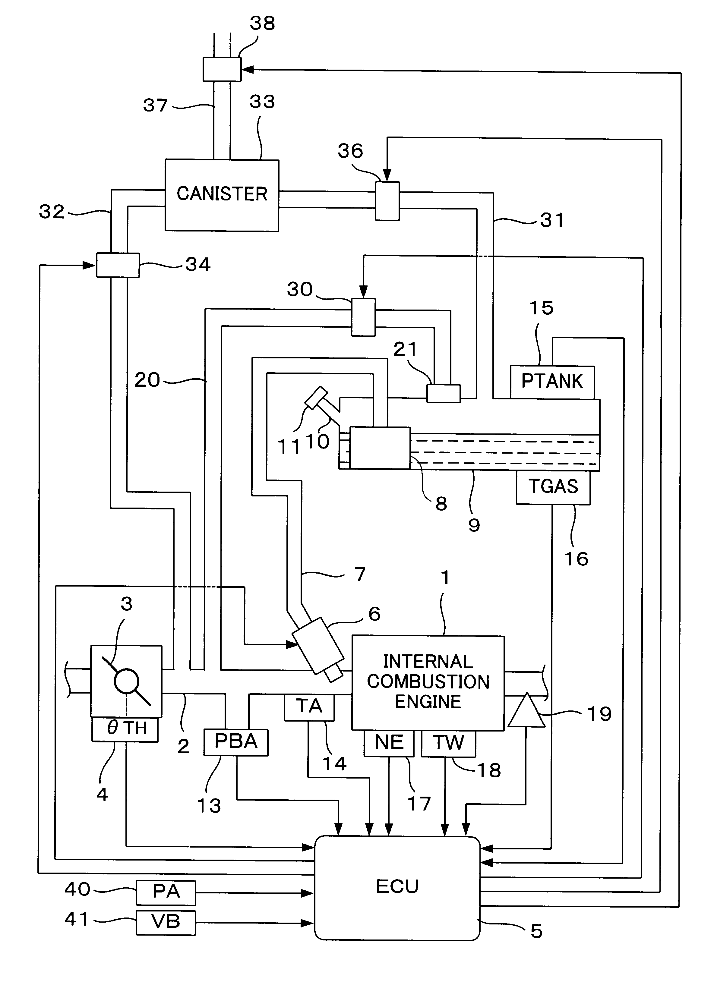
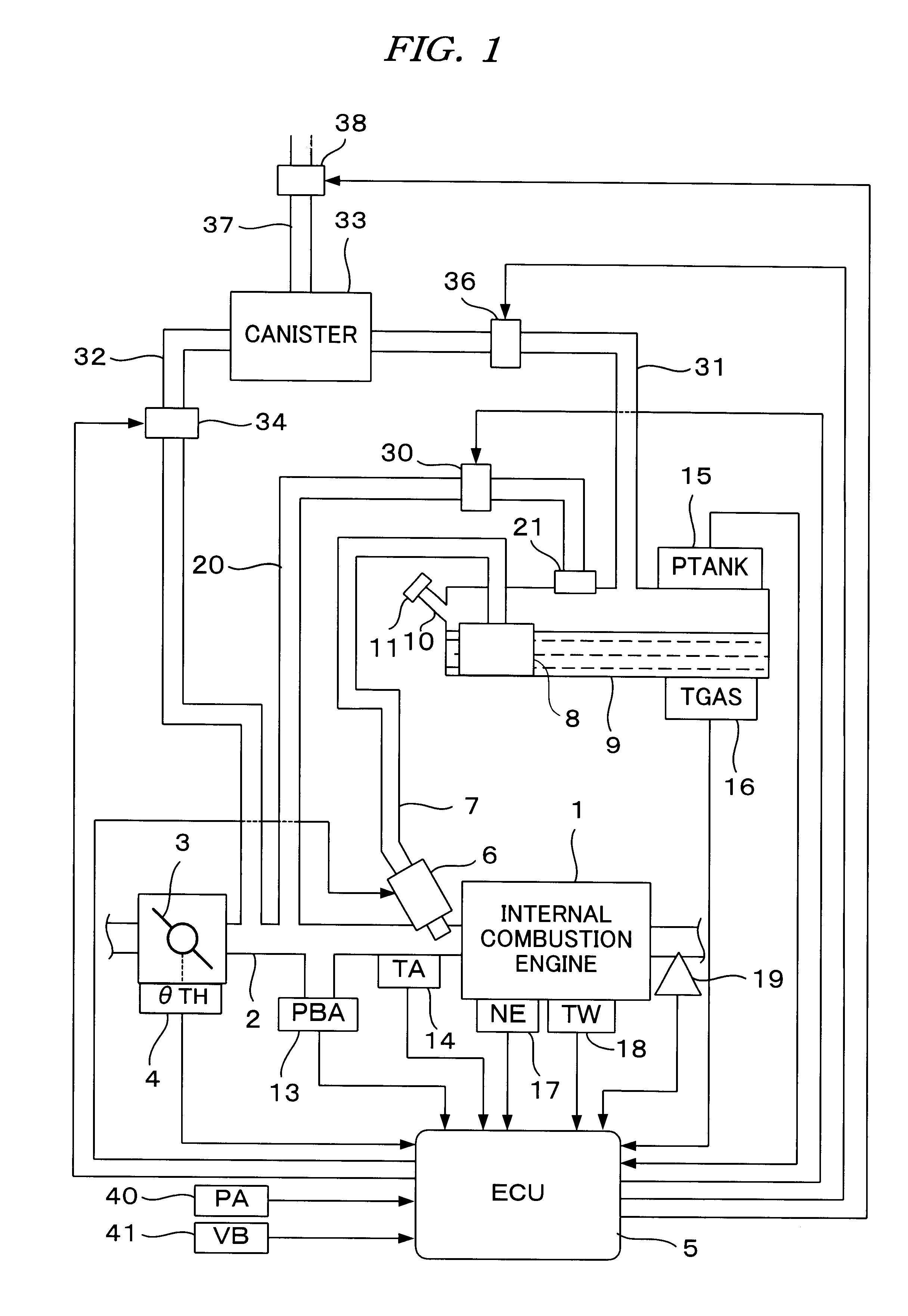
FIG. 1 is a schematic diagram showing the configuration of an evaporative emission control system for an internal combustion engine according to a preferred embodiment of the present invention. Referring to FIG. 1, reference numeral 1 denotes an internal combustion engine (which will be hereinafter referred to simply as "engine") having a plurality of (e.g., four) cylinders. The engine 1 is provided with an intake pipe 2, in which a throttle valve 3 is mounted. A throttle valve opening .theta.TH sensor 4 is connected to the throttle valve 3. The throttle valve opening sensor 4 outputs an electrical signal corresponding to the opening angle of the throttle valve 3 and supplies the electrical signal to an electronic control unit (which will be hereinafter referred to as "ECU") 5.

Fuel injection valves, only one of which is shown, are inserted into the intake pipe 2 at locations intermed...


PUM


Abstract

Disclosed herein is an evaporative emission control system which can properly control the ratio between a tank purge amount and a canister purge amount to realize quick pressure reduction in a fuel tank and ensuring the storage capacity of a canister in a well balanced fashion. A target pressure in controlling the pressure in the fuel tank at a negative pressure and a detected pressure in the fuel tank are compared with each other. When the difference between the target pressure and the detected pressure is large, tank purge is preferentially carried out to open a tank pressure control valve. When the detected pressure is in the vicinity of the target pressure, canister purge is preferentially carried out to purge the evaporative fuel stored in the canister.

Description

BACKGROUND OF THE INVENTIONThe present invention relates to an evaporative emission control system for an internal combustion engine, and more particularly to such a system that the emission of evaporative fuel is prevented by maintaining the pressure in a fuel tank at a negative pressure.For example, Japanese Patent Laid-open No. 11-50919 discloses an evaporative emission control system including a passage for connecting a fuel tank directly to an intake system of an internal combustion engine (this passage will be hereinafter referred to as "first evaporative fuel passage") to maintain the pressure in the fuel tank at a negative pressure (a pressure lower than the atmospheric pressure). This conventional system further includes a canister for temporarily storing evaporative fuel, and a passage for connecting the fuel tank through the canister to the intake system of the internal combustion engine (this passage will be hereinafter referred to as "second evaporative fuel passage"). ...

Claims


Application Information

Patent Timeline
IPC IPC(8): F02D41/00F02M25/08F02D41/02
CPCF02D41/0032F02M25/08
Inventor KITAMURA, TORUSUZUKI, NORIOKUROKAWA, NAOHIROISHIGURO, TETSUYA
Owner HONDA MOTOR CO LTD
Why Eureka
Try Eureka