Fixating image in migrating dye indicator
a dye indicator and fixation image technology, applied in the field of fixation image in migrating dye indicator, can solve the problems of blurred indicia, difficult to ascertain the completion of time interval, unintelligible, etc., and achieve the effect of reducing the blurred indicia
- Summary
- Abstract
- Description
- Claims
- Application Information
AI Technical Summary
Benefits of technology
Problems solved by technology
Method used
Image
Examples
example 1
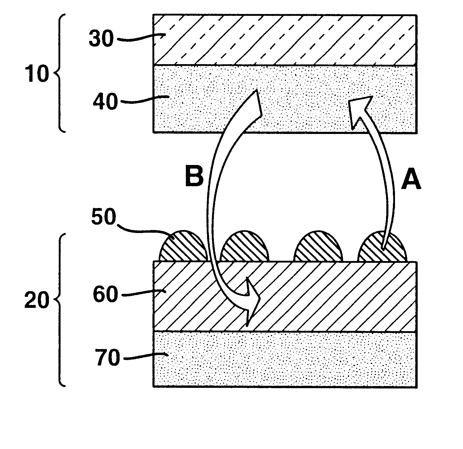
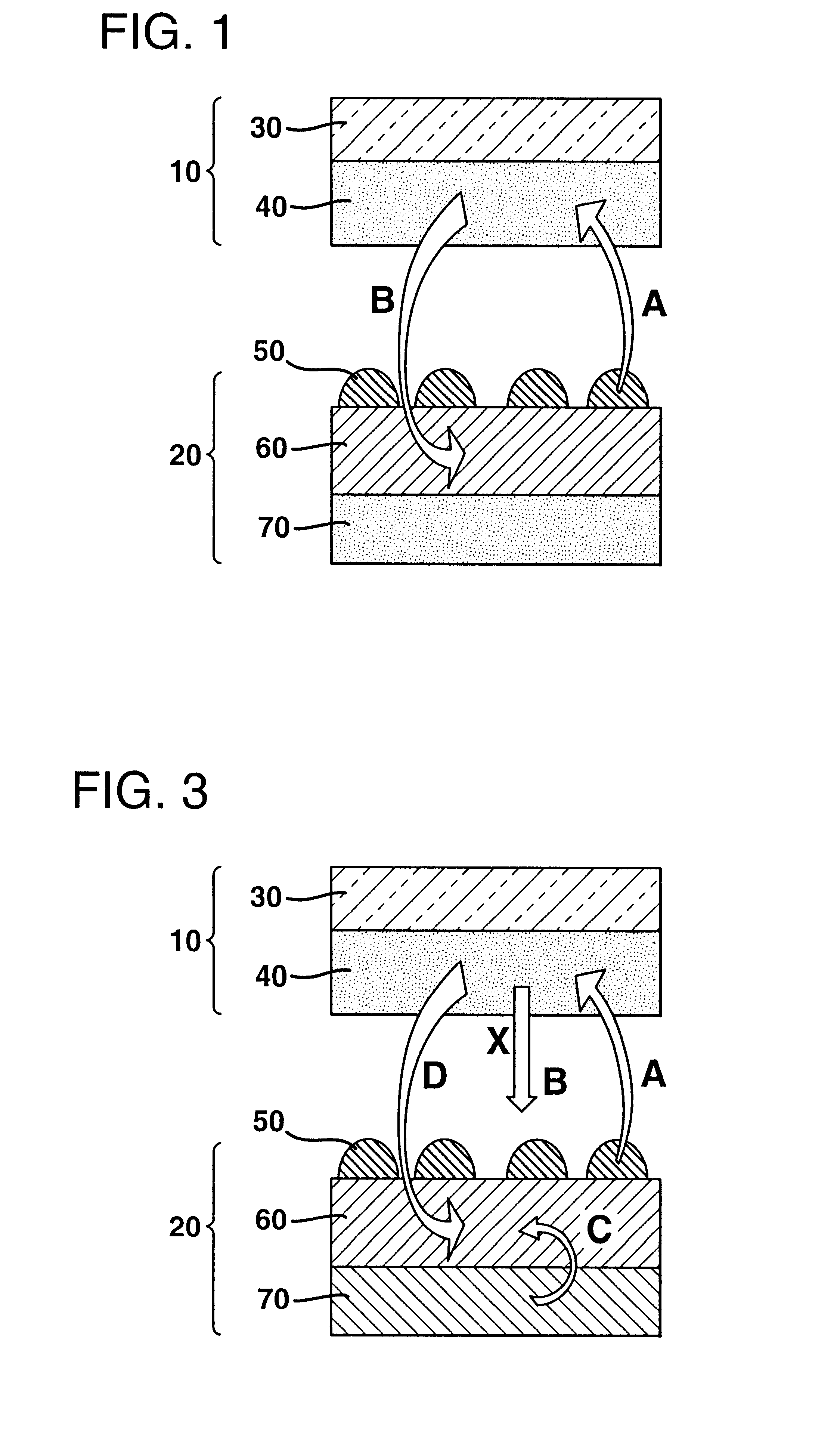
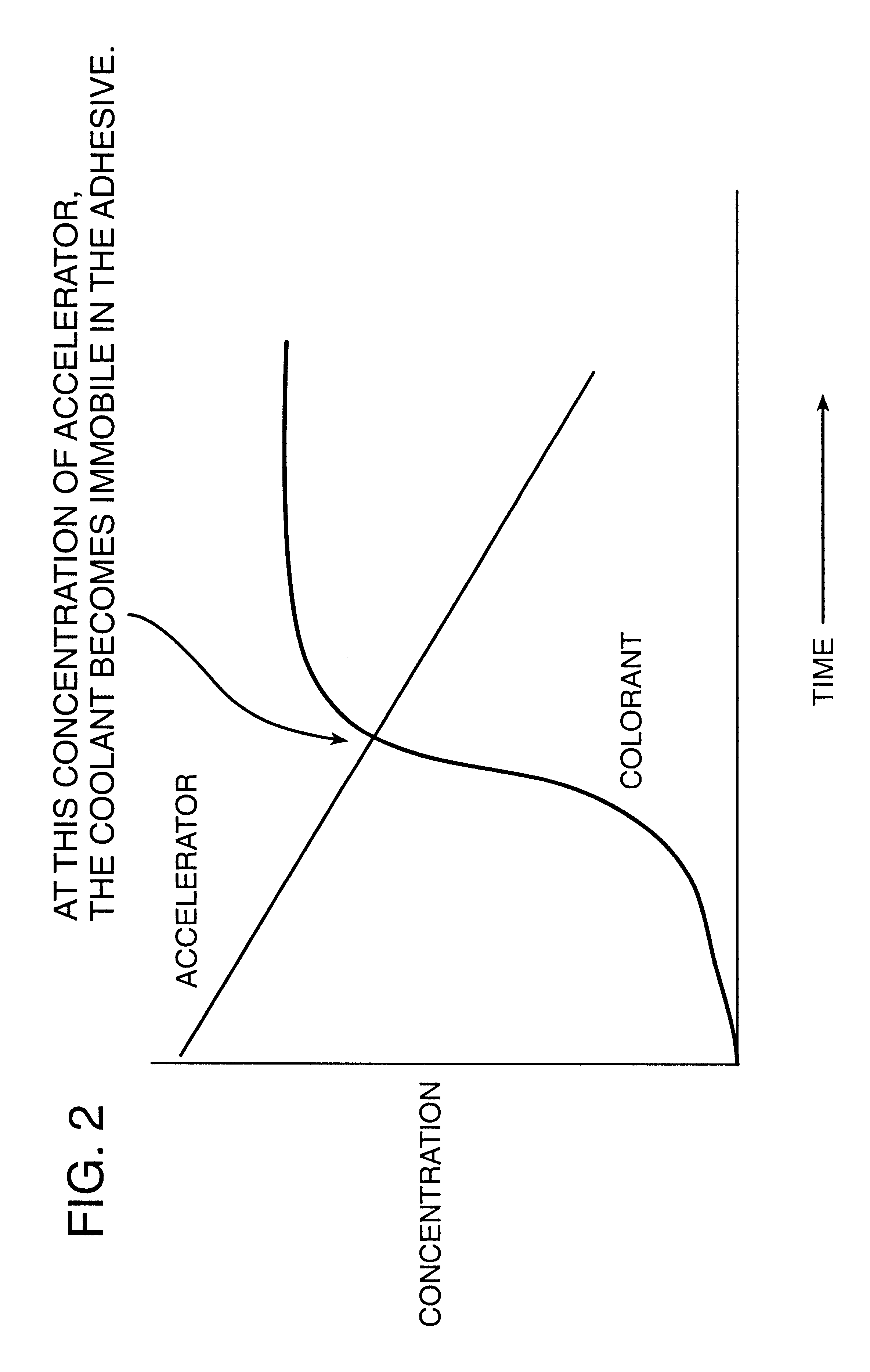
A water emulsion adhesive composed of a vinyl acrylic pressure sensitive adhesive, Covinax 081-01 (Franklin International, Columbus, Ohio) and a compatible plasticizer (accelerator) (Polyethylene Glycol 400, Carbowax 400, Union Carbide, Danbury, Conn.) was prepared and applied to the polyester sheet 30. The plasticizer (accelerator) comprised about 20% polyethylene glycol 400 and 80% Covinax 081-01 (wet weight %).
The plain paper label base layer 20 was printed with an ink containing the dye (FD&C Red #3, Pylam, Tempe, Ariz. The clear display layer 10 formed from the polyester sheet 30 with the adhesive layer thereon, including the accelerator, was placed over the printed plain paper label base layer 20 and allowed to stand. After the image was produced, the dye began to diffuse laterally for a small distance and stopped. A clear visual image was produced and remained constant over a period of time. Visual evidence indicated that the accelerator was absorbed into the base layer. In o...
example 2
A water emulsion adhesive composed of a vinyl acrylic pressure sensitive adhesive, Covinax 081-01 (Franklin International, Columbus, Ohio) and a compatible plasticizer (accelerator) of 20% dibutyl phthalate plasticizer, Plasthall DBP (C.P. Hall, Chicago, Ill.) was prepared and applied to the polyester sheet 30.
The plain paper label base layer 20 was printed with an ink containing the dye (FD&C Red #3, Pylam, Tempe, Ariz. The clear display layer 10 formed from the polyester sheet 30 with the adhesive layer thereon, including the accelerator, was placed over the printed plain paper label base layer 20 and allowed to stand. After the image was produced, the dye began to diffuse laterally for a small distance. A clear visual image was produced and eventually blurred over a period of time. Visual evidence indicated that substantially no accelerator was absorbed into the base layer.
example 3
An adhesive composed of Polytac 213 (H&N Chemical Company, Totowa, N.J.) and a compatible plasticizer (accelerator) of 20% glutarate plasticizer, Plasthall 7050 (C.P. Hall, Chicago, Ill.) was prepared and applied to the polyester sheet 30.
The plain paper label base layer 20 was printed with an ink containing the dye (FD&C Red #3, Pylam, Tempe, Ariz.). The clear display layer 10 formed from the polyester sheet 30 with the adhesive layer thereon, including the accelerator, was placed over the printed plain paper label base layer 20 and allowed to stand. After the image was produced, the dye began to diffuse laterally for a small distance. A clear visual image was produced and eventually blurred over a period of time. Visual evidence indicated that substantially no accelerator was absorbed into the base layer.
A polar dye such FD&C Red #3 will migrate in a polar plasticized acrylic pressure sensitive adhesive (PEG 400--see Example 1 above). If the adhesive changes to a less polar enviro...
PUM
| Property | Measurement | Unit |
|---|---|---|
| of time | aaaaa | aaaaa |
| wet weight % | aaaaa | aaaaa |
| pressure sensitive | aaaaa | aaaaa |
Abstract
Description
Claims
Application Information
 - R&D
- Intellectual Property
- Life Sciences
- Materials
- Tech Scout
- Unparalleled Data Quality
- Higher Quality Content
- 60% Fewer Hallucinations
Browse by: Latest US Patents, China's latest patents, Technical Efficacy Thesaurus, Application Domain, Technology Topic, Popular Technical Reports.
© 2025 PatSnap. All rights reserved.Legal|Privacy policy|Modern Slavery Act Transparency Statement|Sitemap|About US| Contact US: help@patsnap.com


