
System for identifying a component with physical characterization

a physical characterization and component technology, applied in the direction of resistance/reactance/impedence, testing circuits, instruments, etc., can solve the problems of inability to identify components with physical characteristics, inability to meet the requirements of manufacturing environment, and failure of identification forms

Inactive Publication Date: 2001-09-11
MICRON TECH INC
View PDF11 Cites 59 Cited by
  • Summary
  • Abstract
  • Description
  • Claims
  • Application Information

AI Technical Summary

Problems solved by technology

This component identification and information retrieval method is effective; however, the required added step of applying barcodes to the components makes the process less efficient within the production environment.
This form of identification can also fail if the barcode label is lost, obscured or sufficiently damaged.
Unfortunately, however, a limited number of component manufacturers utilize fuse identification.
Therefore, this identification / information retrieval scheme is only effective for a qualified homogeneous set of components; thus, an acceptable "batch" of interchangeable components could not include components supplied from a variety of manufacturers.
A drawback of this identification method, however, is that, particularly with low error rate components, a relatively large number of bit locations must be used for the partial bit map identifier in order to produce a unique `fingerprint` for each component.
Thus, with this scheme, excessive time is required for initial or subsequent identification of a given component.
Further, being based on errors, it does not work for devices with no defects or for devices with a low bit count where there may exist no real or distinct pattern of bit-level errors.

Method used


Image

  • System for identifying a component with physical characterization
  • System for identifying a component with physical characterization
  • System for identifying a component with physical characterization

Examples


Embodiment Construction

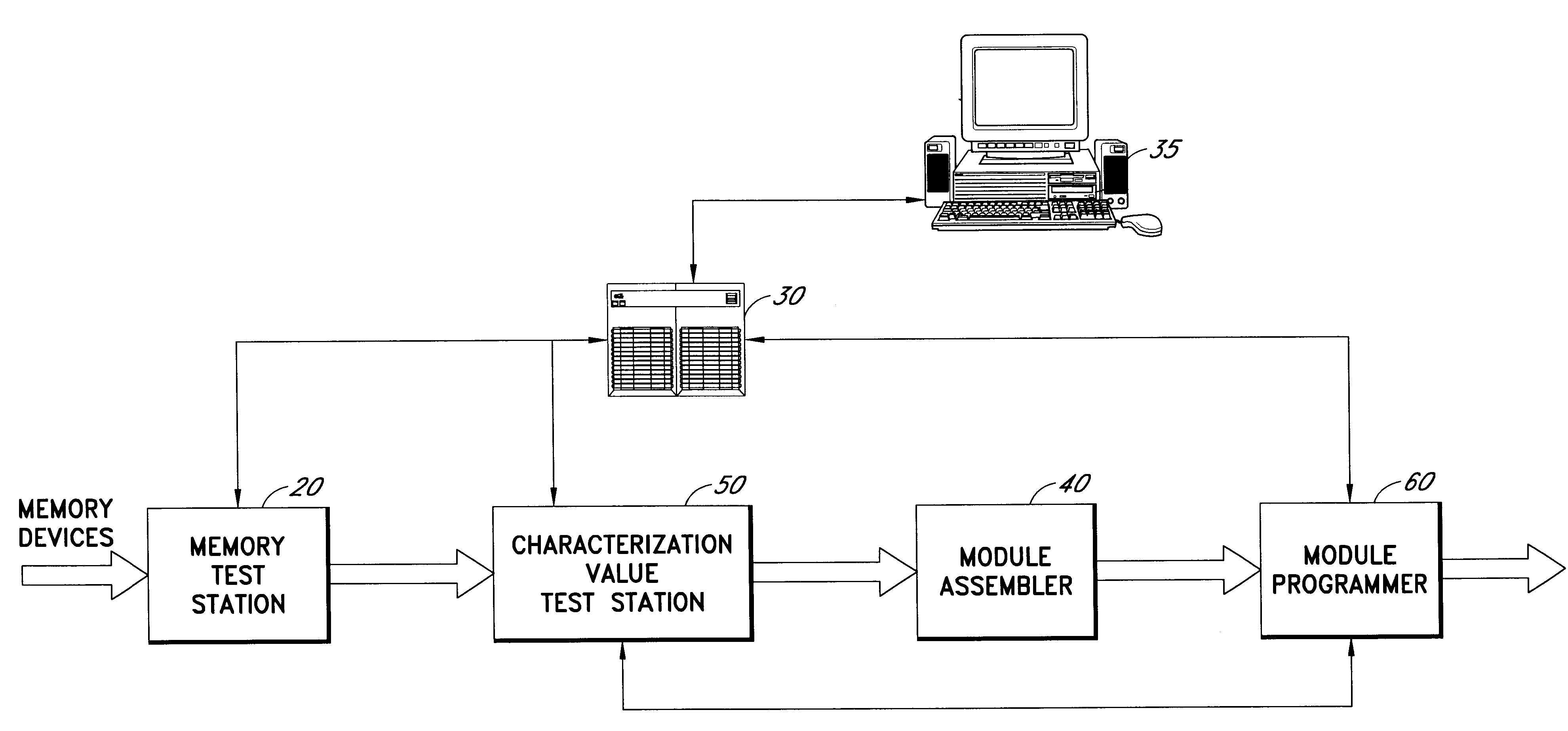
The present invention relates to the identification of electronic components based upon selected inherent physical characteristics. Electronic component identification by physical characterization, as will be discussed in greater detail below, may be utilized in a variety of settings. In particular, physical characterization identification of components may be exploited in various production applications including component information retrieval, module programming, and component manufacturing quality control. Identification by physical characterization is beneficial because added identification "tags" or "marks" (e.g., barcodes, fuse identification numbers) are not required. In addition, a sufficient number of physical characteristics, which are necessary to produce a unique identification value for each component, may be measured in a relatively minuscule amount of time, thereby making this process valuable in a production environment.

As used herein, the term "component" includes ...


PUM


Abstract

With the present invention, a component may be identified based upon selected physical characteristics of the component. In one embodiment, a system is provided for storing information pertaining to components within a set of components. A characterization function, which is a function of relevant physical characteristics shared by each component within the set of components, is associated with the set of components. The system includes a characterization value test station and a database. The characterization value test station is used to determine the characterization values of the components pursuant to the characterization function. The database stores information that pertains to each component with the component's characterization value linked as an identifier to the information. In this manner, information pertaining to a component may be retrieved from the database based on the component's characterization value.

Description

1. TECHNICAL FIELDThe present invention relates generally to electronic component identification. In particular, the present invention relates to the identification of electronic components based on their physical characteristics.2. BACKGROUND OF THE INVENTIONMany electronic devices are based on modules made by combining a number of components on a printed circuit board or other substrate. Examples are personal computer motherboards, fax modem add-on boards, memory modules (e.g., DRAM, SDRAM), and device controller boards. For various reasons, it is important to be able to automatically and efficiently identify, throughout the manufacturing process, the individual components that are combined to form an electronic module. The assigned identifier can then serve as the key or label for (or in) one or more files (usually electronic) that relate to the individual component. For example, after components have been installed into a module, it may be desirable to program individual compone...

Claims


Application Information

Patent Timeline
Patent Type & Authority Patents(United States)
IPC IPC(8): G01R31/28G01R31/317
CPCG01R31/317
Inventor CHARLTON, DAVE E.OCHOA, ROLAND
Owner MICRON TECH INC
Learn More