Magnetic head slider manufacturing method
a manufacturing method and slider technology, applied in the field of magnet head, can solve the problems of poor product quality, hindering the achievement of the desired cavity shape, and difficult manufacturing of the type of cavity
- Summary
- Abstract
- Description
- Claims
- Application Information
AI Technical Summary
Problems solved by technology
Method used
Image
Examples
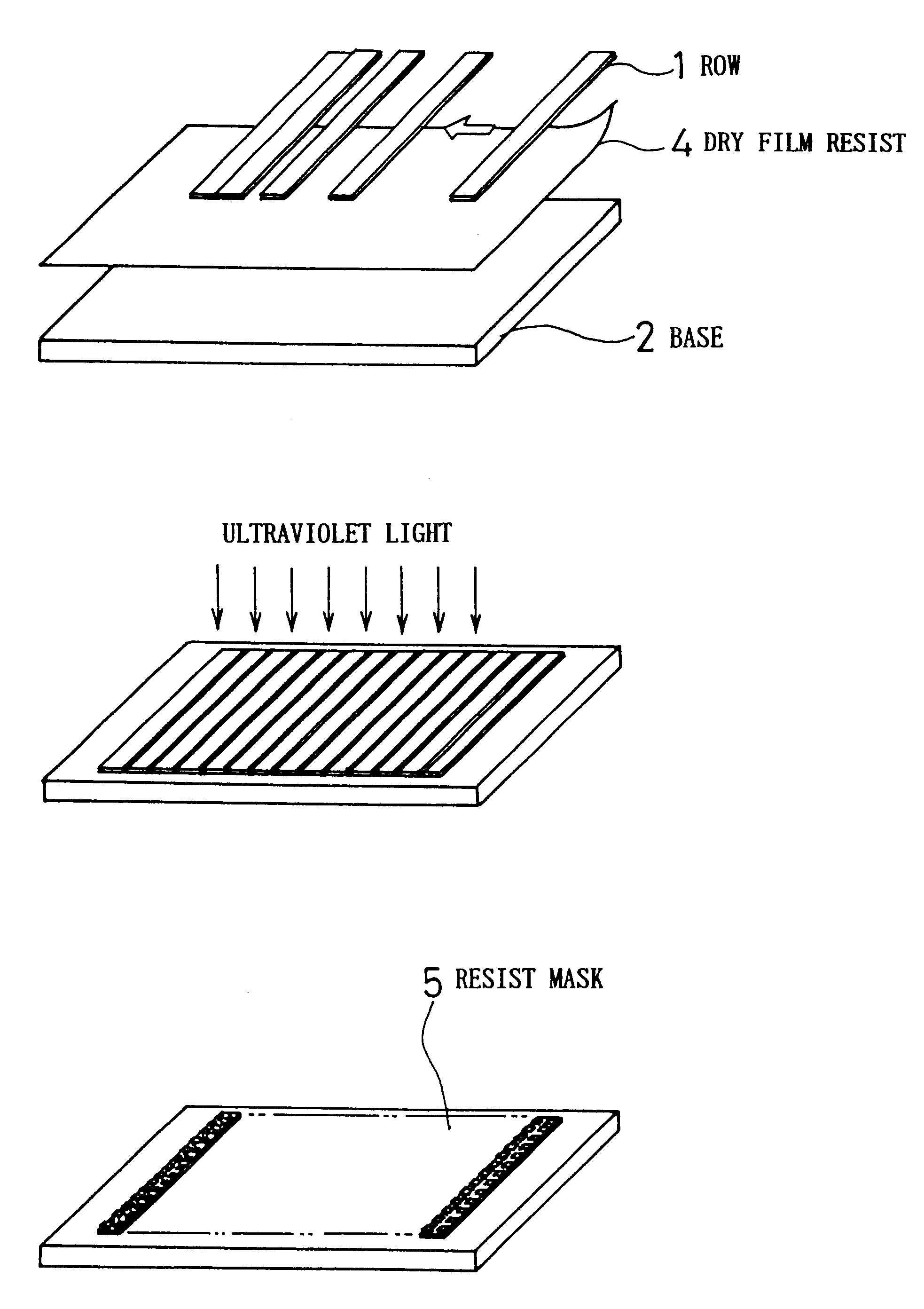
first embodiment
Similar to the case of the first embodiment, it is possible to increase the radio-frequency output to 1.5 times of what it was with the previous method of using wax as an adhesive, this enabling not only a 20%-improvement in etching speed, but a low failure rate as well.
third embodiment
Next, the constitution of the present invention will be described.
Specifically, although this was not specifically mentioned with regard to two above-noted embodiments, as shown in FIG. 6, this has a pad 9 for the purpose of connection to the magnetic head element built into the side surface of the air bearing of the row bar, so that rows are not brought into intimate contact with and adhered to one another.
For this reason, plasma that flows in from the space between rows can destroy the pad 9, and the accumulation of materials sputtered from an opposing row, this being the sputter layer 10, was viewed as a problem.
This is illustrated in FIG. 6. There was a need also to solve the problem of these phenomena, which caused a loss of connectivity of the pad and problems with quality of appearance.
Because of this situation, in this embodiment in performing the same types of operations as described with regard to the foregoing embodiments, a base 2 was used that has a groove 12 that is sl...
fourth embodiment
Next, yet another magnetic head slider manufacturing method, the present invention, will be described, this description being for the example of using a base 2 having a cross-section as shown in FIG. 4(A).
In this example, one side surface 13 of the groove 12 is cut so as to stand perpendicularly so that it protects the row 1 element surface, while the other 14 is formed as an inclined surface to facilitate alignment.
The condition after adhering the rows 1 is shown in FIG. 4(B). Upon manufacturing a magnetic head slider using this type of base and the manufacturing method indicated as the third embodiment, the same type of good results were obtained, without any difference with respect to the third embodiment.
PUM
| Property | Measurement | Unit |
|---|---|---|
| thickness | aaaaa | aaaaa |
| temperature | aaaaa | aaaaa |
| temperature | aaaaa | aaaaa |
Abstract
Description
Claims
Application Information
 - R&D
- Intellectual Property
- Life Sciences
- Materials
- Tech Scout
- Unparalleled Data Quality
- Higher Quality Content
- 60% Fewer Hallucinations
Browse by: Latest US Patents, China's latest patents, Technical Efficacy Thesaurus, Application Domain, Technology Topic, Popular Technical Reports.
© 2025 PatSnap. All rights reserved.Legal|Privacy policy|Modern Slavery Act Transparency Statement|Sitemap|About US| Contact US: help@patsnap.com


