
Clip type fastener assembly

Inactive Publication Date: 2001-09-11
SOUTHCO
View PDF40 Cites 88 Cited by
  • Summary
  • Abstract
  • Description
  • Claims
  • Application Information

AI Technical Summary

Benefits of technology

Accordingly, it is desirable to have a clip nut type device which inhibits corrosion of the nut member and the surrounding support structure. Additionally, it is desirable to have a clip nut device which can be relatively inexpensive to manufacture and can be employed by the end user at a reasonable installation cost. Furthermore, it is desirable to have a clip nut device which securely maintains its relative position alignably with the hole or opening formed in the support structure for use in the subsequent assembly of another member to the support structure. In this regard it is desirable to have a clip nut device which locks to itself thereby assuring maintenance of its relative position alignably with the opening formed in the support structure to facilitate the subsequent assembly of the other member. It is also desirable to have a clip nut device which is not dimensionally sensitive and which can be locked onto panels or support members having a significant range of thicknesses.
Here the threaded nut member, preferably, is of a metallic structure to provide adequate strength when engaged with a mating metal screw or bolt; however, the nut member is held and substantially encapsulated in the second bushing at one end of the second bore at a position spaced from engagement with the surface of the support structure to which it is to be preassembled thereby avoiding galvanic type corrosion.
It is another object of the present invention to provide such a unique clip nut which can be used with support structures having a predetermined range of thicknesses.

Problems solved by technology

Clip nuts are commonly used in applications where access to either side of a panel or member will be limited for subsequent assembly of a related member so that manually holding a nut behind the hole or opening formed in the panel, or member is difficult or impossible.
Such metal clip nuts, when used for applications in areas exposed to significant moisture tend to cause galvanic corrosion around the area of application of the clip nut.
In some cases lightweight, titanium clip nuts may be actually required in problem areas, but are more costly than cadmium-plated steel clip nuts.
The high cost of the titanium clip nuts can present a significant cost problem for example, in the manufacture of aircraft since a great number of clip nuts, may be used on a single aircraft.
The Benn patent's clip-on nut, however, is constructed from a bendable steel material which while cadmium plated may still may be subject to corrosion as noted above.
None of the above, however, show a device which can accommodate significant variations in the thickness of the panels to which they are to be secured.
Also, none of the above devices including the '264 Benn patent appear to show a clip type device with a generally hole filling feature for resisting vibrational loads.
In addition none show a device in which a metal nut member is substantially encapsulated in a plastic material.

Method used


Image

  • Clip type fastener assembly
  • Clip type fastener assembly
  • Clip type fastener assembly

Examples


Embodiment Construction

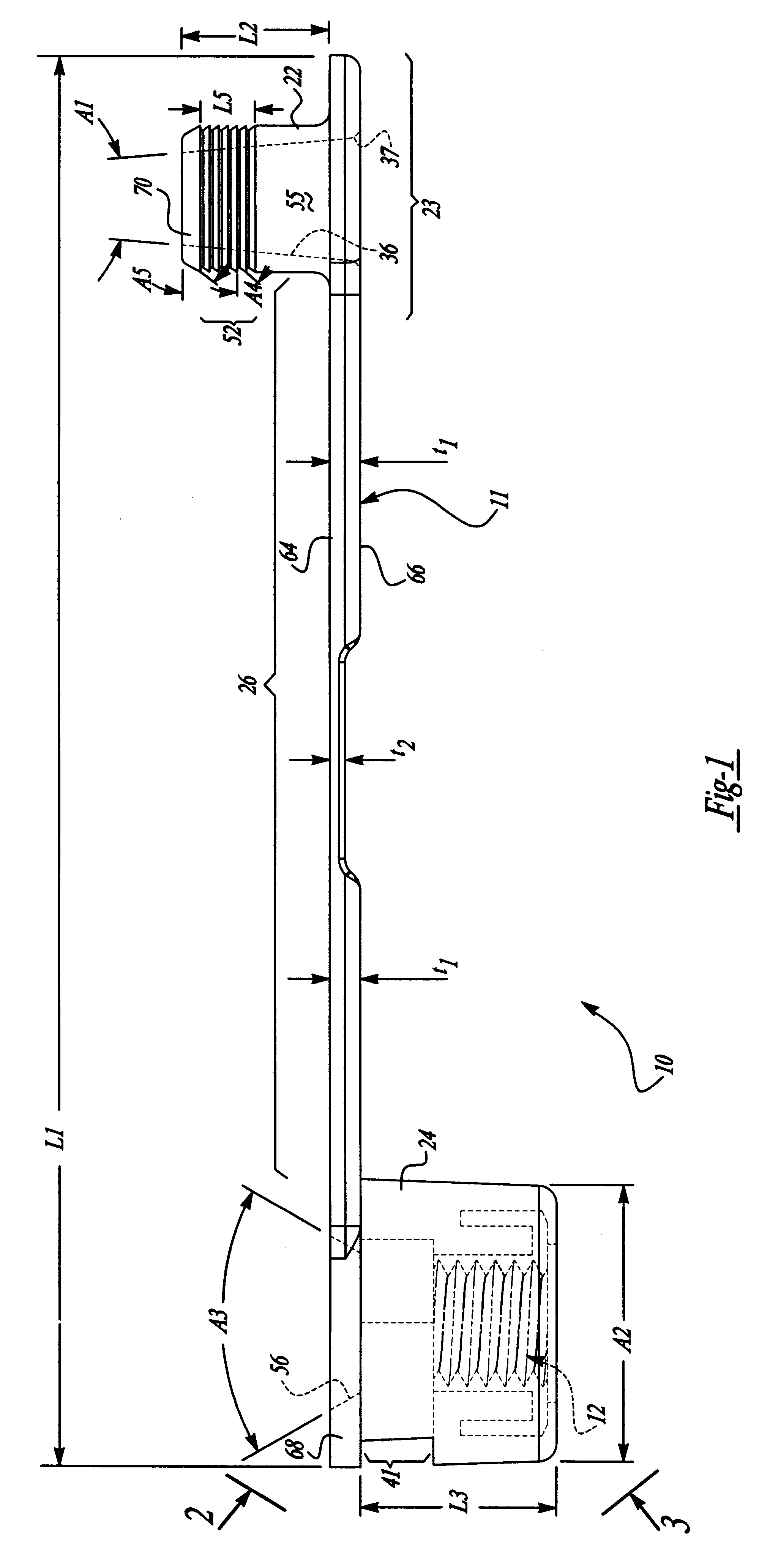
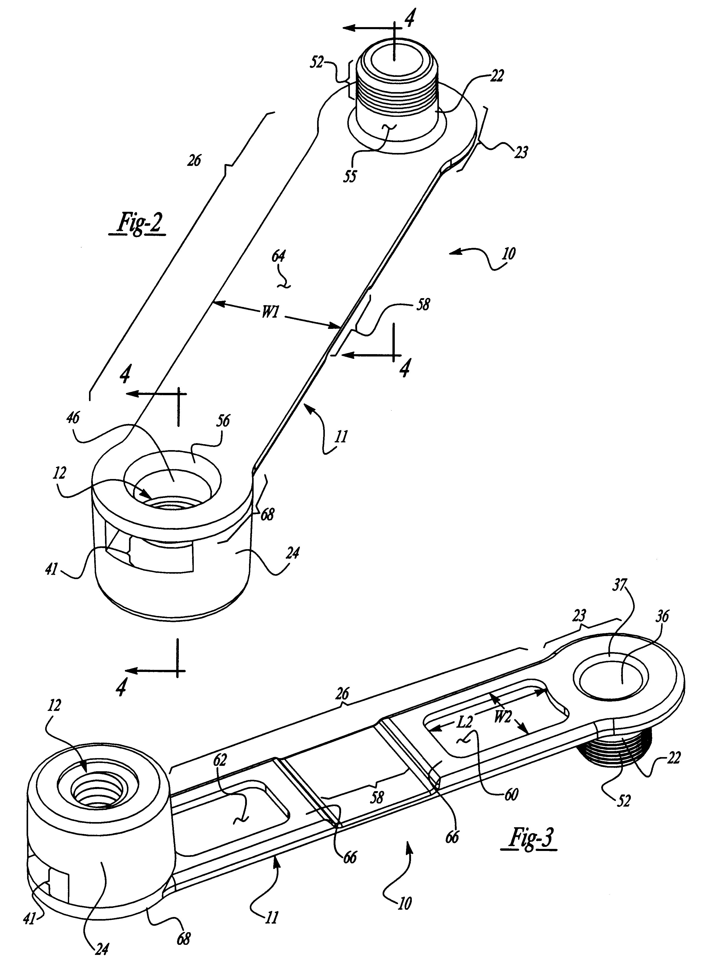
Looking now to the drawings, a clip nut device 10 is shown and includes an elastomeric body member 11 with a threaded nut member 12 secured therein. As illustrated in FIGS. 4 and 5 the body member 11 is operative to align the nut member 12 with a hole or opening 14 in a support structure 16 which has generally planar upper and lower surfaces 28 and 30, respectively. The clip nut device 10 of the present invention retains the threaded nut member 12 in a preselected position adjacent an edge or end surface 18 of the support structure 16 and in line with the opening 14 for receiving the shank 21 of a screw or bolt 20 and guiding the threaded shank portion 21a for threaded engagement with the aligned nut member 12. The shank 21 has a smooth shank portion 21b which is connected to an enlarged countersunk or flush type head 21c.

The body member 11 of the clip nut device 10 of the present invention includes a first projecting member or bushing 22, a second projecting member or bushing 24, a...


PUM


Abstract

A clip type nut device for attachment about an aperture or opening of a support structure is provided with the clip nut device having a resilient main body member having a pair of transversely oppositely extending bushings at opposite ends of a flexible strap with a captured nut member in one bushing. One bushing has a first opening and is receivable within the support structure opening. The other or second bushing has a second opening with the threaded nut member captured in the second opening. A securing structure associated with the first and second bushing is operable to secure the first bushing to the second bushing with the first opening being aligned with the second opening such that the threaded nut member is aligned with the opening through the support structure.

Description

SUMMARY BACKGROUND OF THE INVENTIONThe present invention relates to clip type fastener assemblies which include a nut section on one end of a flexible strap or an arm which is self-securing to an opening or hole formed in a support structure to receive a bolt inserted through the hole and tightened into the nut section for fastening another member to the support structure.Such fastening devices have been frequently referred to as clip nuts, clip-on nuts, etc. Clip nut devices are generally well known and include a nut section which can be positioned behind or underneath a panel or other similar flat surface to which another panel or other member is to be joined. Such clip nut devices usually include an arm which is resiliently movably connected to the nut section and is spaced in a preset position opposite the nut section by which the clip nut device can be resiliently clamped in place.Clip nuts are commonly used in applications where access to either side of a panel or member will ...

Claims


Application Information

Patent Timeline
IPC IPC(8): F16B37/04F16B37/12F16B37/00
CPCF16B37/043Y10S411/903F16B37/122
Inventor JHUMRA, KHUSRO M.SCHERER, RAYMOND C.TARR, LARRY E.
Owner SOUTHCO
Learn More