
Submersible in-situ oxygenator

a technology of oxygenator and in-situ oxygen, which is applied in the direction of machines/engines, chemical/physical processes, domestic heating, etc., can solve the problems of contaminating soil or underground water, no longer allowing wastewater containing land-banned chemicals, and many potential environmental problems of construction

Inactive Publication Date: 2001-08-14
PRAXAIR TECH INC
View PDF17 Cites 71 Cited by
  • Summary
  • Abstract
  • Description
  • Claims
  • Application Information

AI Technical Summary

Benefits of technology

It is another object of the present invention to provide an apparatus and method to aerate liquid and agitate solids in a deep tank using the minimum energy required.
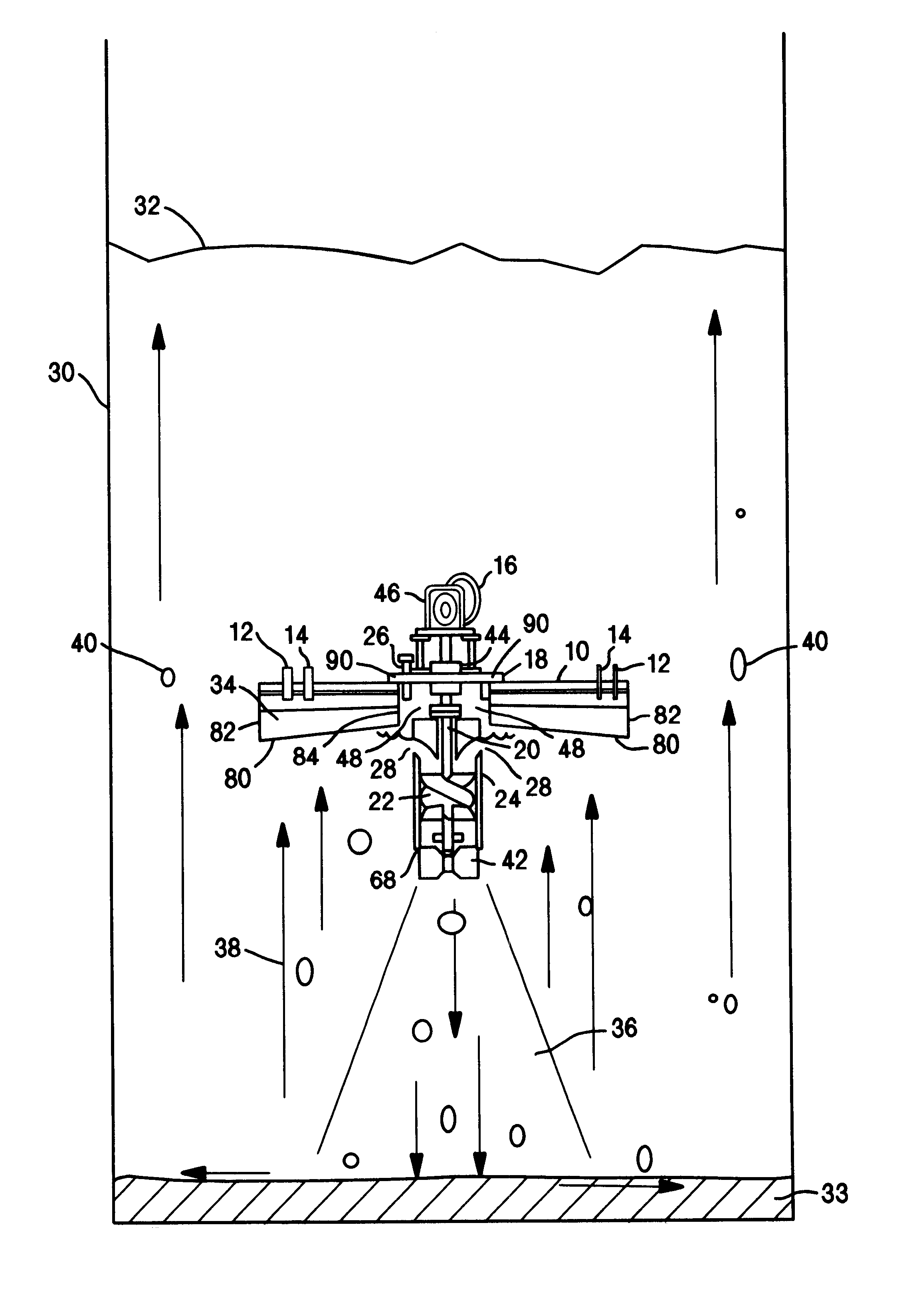
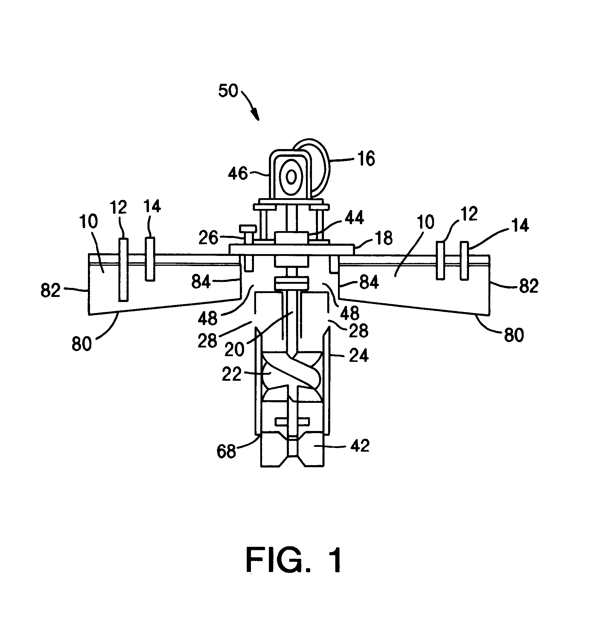
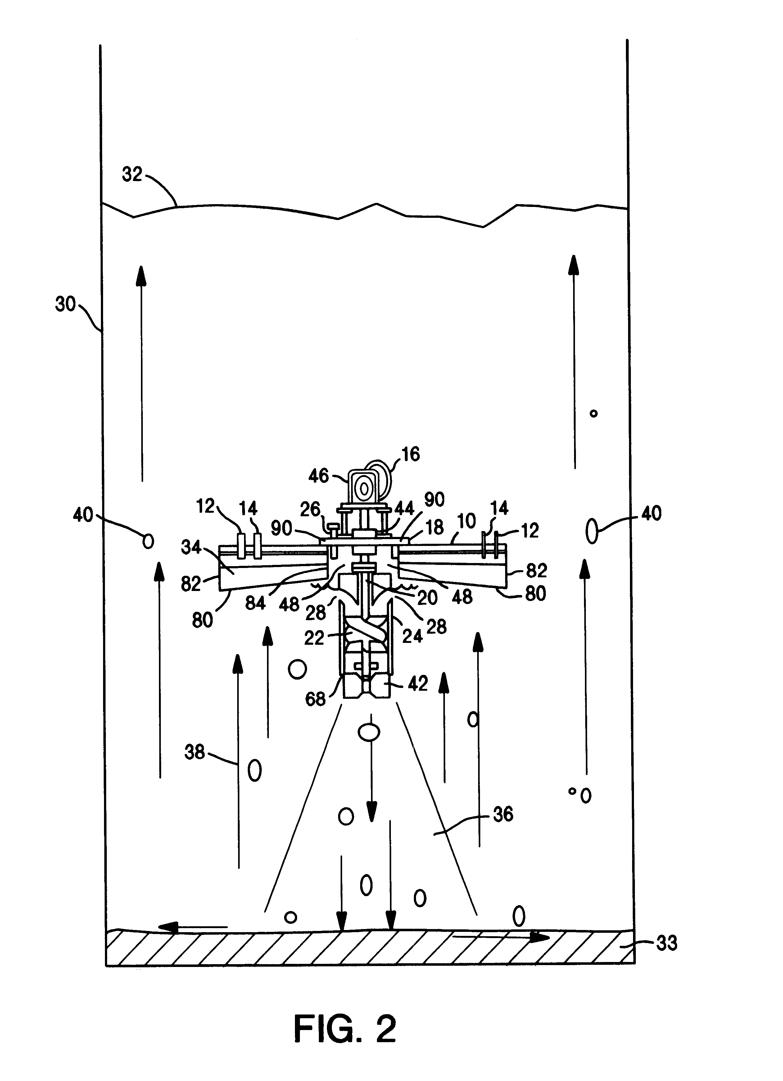
In the preferred embodiment, the fluid pump comprises an impeller connected to a rotatable shaft disposed within a draft member. The draft member is adapted to draw the gas and liquid from the body of liquid into the draft member through an opening near the top of the draft member above the impeller and to exit through a second opening at a lower end of the member. The impeller is connected to the shaft and adapted to draw the gas and liquid into the draft member towards the impeller and cause the gas-liquid mixture to exit the draft member at a high velocity. The impeller may be a high capacity impeller, a gas dispersion impeller, particularly that which is helical in shape and adapted to circulate large volumes of the gas and the liquid. The feed gas stream is directed into a headspace above the impeller through a feed gas inlet. The feed gas stream may also be introduced directly into a vortex formed by the impeller as it rotates into the liquid. In the most preferred embodiment, a turbulent promoter to increase the turbulent mixing of the gas-liquid mixture may be connected to the shaft.

Problems solved by technology

However, this type of construction poses many potential environmental problems.
Hazardous chemical compounds can seep through the bottom of an earth base basin, thereby contaminating the soil or underground water.
The Environmental Protection Agency will no longer allow wastewater containing land-banned chemicals, such as benzene, to be treated in these facilities, due to the contamination hazard.
Thus, the large shallow earth basin is losing its status as the preferred kind of aeration pond.
The above ground tanks, with steel bottoms, will not allow toxic chemicals to penetrate the tank and contaminate the surrounding areas and have less surface-to-volume ratio for fugitive emissions.
Supplying oxygen to such deep tanks is a challenge with conventional wastewater aeration devices.
Surface aerators can only provide a sufficient supply of oxygen to the top layer of the whole wastewater tank.
Fine bubble diffusers require a large amount of horsepower to compress the air and overcome the hydrostatic head of the aerators.
To allow the biomass to function properly, the sludge must be adequately suspended, or segregation will occur, resulting in poor biodegradation of the waste.
Prior art surface aeration devices do not effectively address the issue of sludge at the bottom of a deep tank.
Re 32,562, to enhance the dissolution of oxygen from an overhead space, has limited effectiveness in a deep tank.
Since the device is fixed on the reactor vessel, it is not possible to optimize solid suspension.
However, there are practical limitations as how fast a helical impeller can rotate.
Even if the mechanical difficulties are overcome, the system will require tremendous amount of power for the agitation.
Much of this power is wasted.
It does not make sense to waste this energy while the oxygen dissolution function requires only a small amount of energy.
At one point, the jet stream will weaken to a point that it can no longer carry the oxygen bubbles downward.
The liquid jet is so weak that it will not be able to travel any further or provide agitation to the bottom part of the tank.
However, significant power is still required to drive the agitator at the bottom of the tank, increasing capital expenditure.

Method used


Image

  • Submersible in-situ oxygenator
  • Submersible in-situ oxygenator
  • Submersible in-situ oxygenator

Examples


Embodiment Construction

)

In describing the preferred embodiment of the present invention, reference will be made herein to FIGS. 1 to 3 of the drawings in which like numerals refer to like features of the invention. Features of the invention are not necessarily shown to scale in the drawings.

As shown in FIGS. 1 and 2, the apparatus of the present invention comprises a gas-liquid aerator device 50, adapted to be submerged in deep tank 30 containing liquid 32 and solid 33. In the preferred embodiment, liquid 32 is wastewater and solid 33 is sludge formed in deep tank 30. Device 50 includes a fluid pump, such as an impeller, a jet flow pump or a positive displacement device, which can draw in a liquid and a gas, and cause the movement of the liquid and gas downwardly at a high velocity. In the preferred embodiment, device 50 comprises a submergible motor 16 connected to motor support plate 18 and a rotatable shaft 20. An impeller 22 is connected to shaft 20, and impeller 22 and shaft 20 are preferably dispose...


PUM

PropertyMeasurementUnit
Timeaaaaaaaaaa
Sizeaaaaaaaaaa
Volumeaaaaaaaaaa

Abstract

An apparatus and method for mixing a gas and a liquid while concomitantly mixing and suspending solids and sludge at the bottom of a deep tank. The present invention includes a gas-liquid aerator which is adapted to be submerged below the surface of wastewater in a deep tank. An expanding high velocity gas-liquid mixture is caused to exit from the bottom of the submerged aerator device with enough force to mix and suspend settling solids and sludge at the bottom of the deep tank.

Description

This invention relates generally to the aeration of liquid and solids and in particular to an apparatus and method for dissolving oxygen in a liquid and the concomitant agitation of liquid and solids holding various chemicals.DESCRIPTION OF RELATED ARTAerobic wastewater treatment is a highly economical means to eliminate harmful chemical waste in aqueous systems. Oxygen or air is supplied to the biomass in the wastewater so that toxic or harmful chemicals can be consumed by the biological agents as food to form harmless byproducts. Normally, carbon dioxide and water are the major respiration products.The cheapest form of an aeration pond is an earth base basin whereby the soil is removed from the surface up to 10 to 15 feet (3.0 to 4.6 meters) below the surface. However, this type of construction poses many potential environmental problems. Hazardous chemical compounds can seep through the bottom of an earth base basin, thereby contaminating the soil or underground water. The Enviro...

Claims


Application Information

Patent Timeline
IPC IPC(8): B01F3/04B01F7/00C02F3/20C02F3/12C02F3/16
CPCB01F3/04609B01F7/00733C02F3/206C02F3/1294B01F3/04099B01F2003/0495B01F2003/04879Y02W10/10B01F23/23B01F23/23341B01F23/237612B01F27/25C02F3/16
Inventor CHENG, ALAN TAT YAN
Owner PRAXAIR TECH INC
Learn More