
Method and apparatus for high spatial resolution spectroscopic microscopy

Inactive Publication Date: 2001-07-17
TA INSTR
View PDF14 Cites 31 Cited by
  • Summary
  • Abstract
  • Description
  • Claims
  • Application Information

AI Technical Summary

Benefits of technology

Another object of the present invention is to provide a resistive thermal probe which serves as a point source of heat (in addition to sensing temperature and performing the functions listed in the objects above), such that it can produce the high-frequency temperature modulation that is needed for the user to choose the volume of material being spectroscopically analyzed at each individual location selected.

Problems solved by technology

However, most methods commercially available suffer from the limitations imposed by the finite optical wavelengths of the detection systems used.
For example, in practice the spatial resolution of the popular but expensive technique of Fourier transform infrared microscopy is seldom better than five to ten micrometers.
Previous work on optical absorption spectroscopy combined with near-field microscopy has either been limited to the study of electrically conductive samples or has been restricted to the use of individual wavelengths of the incident light.
Moreover, no reliable way has been described of deconvoluting spatial variations in thermal properties from the local variations in infrared absorption which are the key to localised spectroscopic analysis.

Method used


Image

  • Method and apparatus for high spatial resolution spectroscopic microscopy
  • Method and apparatus for high spatial resolution spectroscopic microscopy
  • Method and apparatus for high spatial resolution spectroscopic microscopy

Examples


Embodiment Construction

(see D. W. van Krevelen, Properties of Polymers, Elsevier 1990)

The calculations below assumes the material has the values of parameters of polyethylene.

Notation:

Thermal conductivity k=0.15 Wm.sup.-1 .degree. KE.sup.-1

Density.times.heat capacity .rho.C.sub.p =10.sup.6 Jm.sup.-3 .degree. K.sup.-1

Diffusivity D=k / (.rho.C.sub.p)=1.6.times.10.sup.-7

Thermal diffusion length .mu. is given by .mu..sup.2 =D / (.pi..nu.), where .nu. is frequency.

Optical absorption length for IR within a typical absorption band:

l.sub..beta. =2.5 .mu.m (absorption coefficient=4.times.10.sup.5 m.sup.-1, but can vary two orders of magnitude from one "edge" to another. With visible light, l.sub..beta. =10.sup.-4.

IR bandwidth (.DELTA..lambda.) chosen: 200 nm.

Thickness of the near-surface layer of interest: z.sub.s =either film thickness, or =.mu., see above ("bulk" samples).

Illuminated area of sample: 1 mm.sup.2

Power of source: 100 mW

Power per nm of the absorption band: 0.7.times.10.sup.-6 (the implied ratio R=1.4.tim...


PUM


Abstract

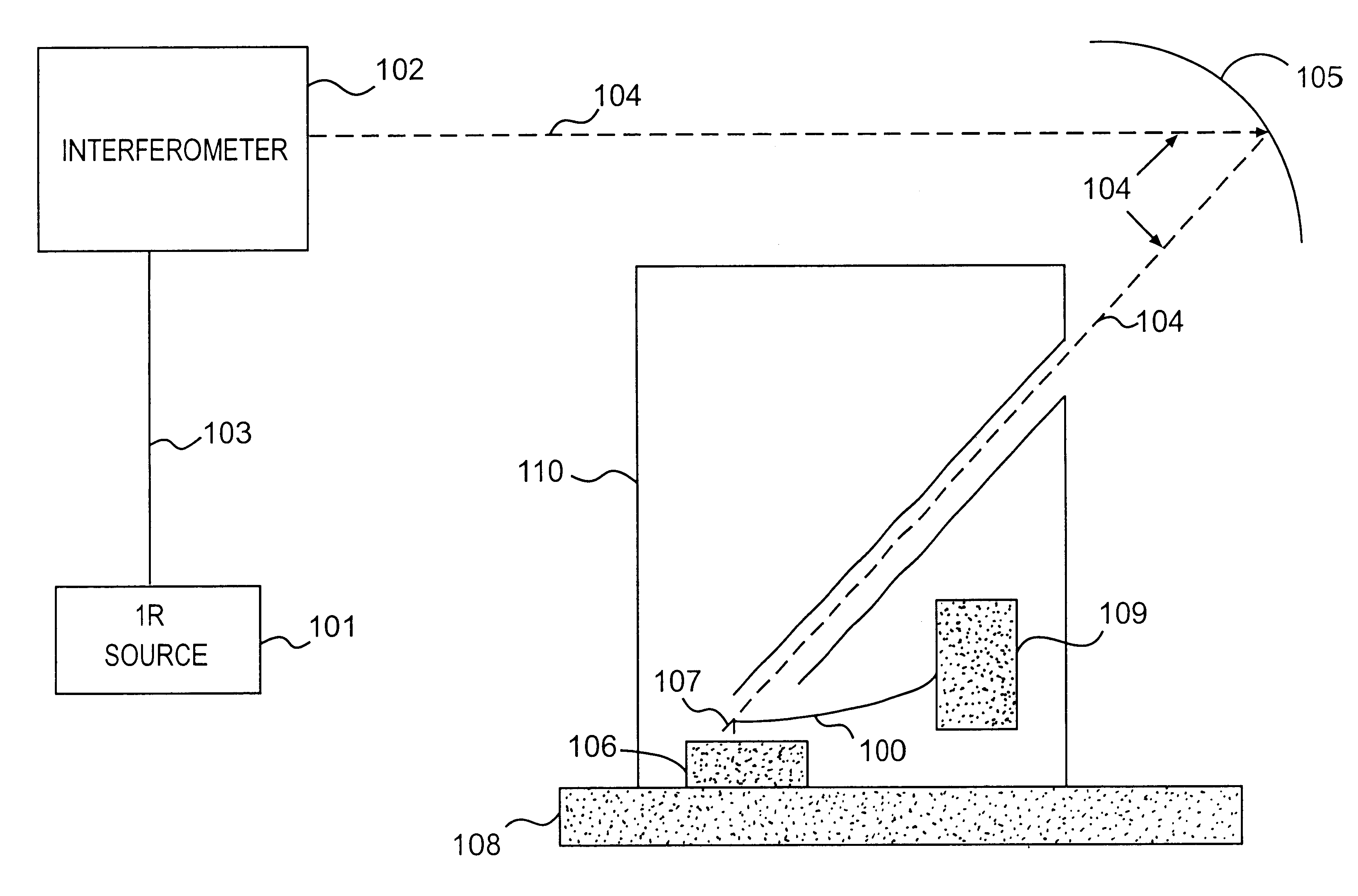
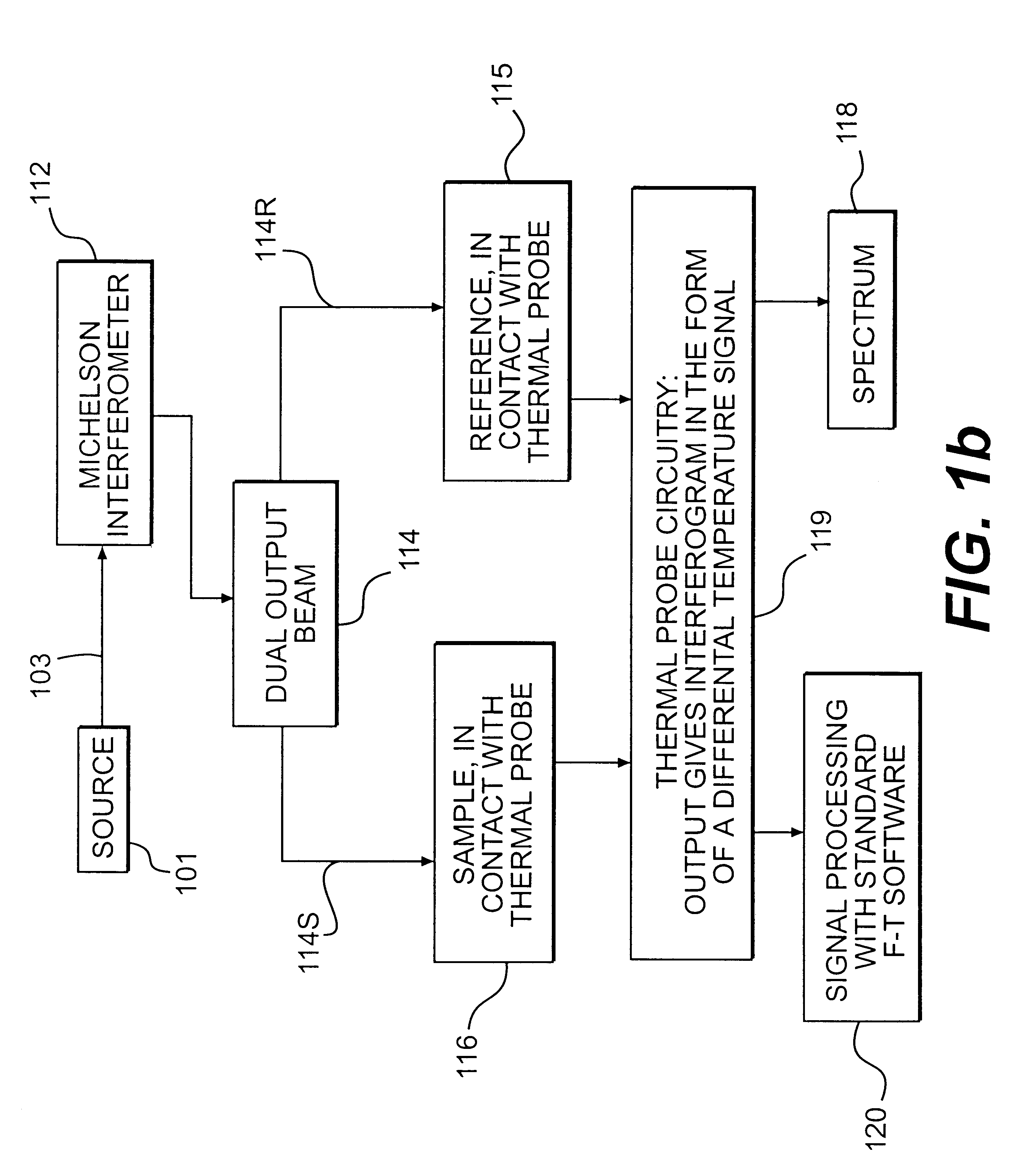
A sample and a scanning probe microscope system are used as the detector for an infrared spectrometer to circumvent the diffraction limit of conventional infrared microscopy, and to provide spectroscopic images with a greatly improved spatial resolution, potentially as low as a few tens of nanometers. The beam from an infrared spectrometer is directed at the sample. The sample is heated to the extent that it absorbs infrared radiation. Thus the resulting temperature rise of an individual region depends upon the particular molecular species present, as well as the range of wavelengths of the infrared beam. These individual temperature differences are detected by a miniature thermal probe. The thermal probe is mounted in a scanning thermal microscope. The scanning thermal microscope is then operated used to produce multiple surface and sub-surface images of the sample, such that the image contrast corresponds to variations in either thermal diffusivity, surface topography or chemical composition.

Description

1. Field of the InventionThe present invention relates to spectroscopic analysis of individual regions of inhomogeneous samples. The regions to be analyzed are identified, selected and imaged at a high spatial resolution using scanning probe microscopy.2. Description of the Related ArtTechniques for the photothermal characterization of solids and thin films are widely used, as is described by D. P. Almond and P. M. Patel, "Photothermal Science and Techniques", Chapman and Hall (London and New York, 1996). Recently the ability to add spatial resolution to these techniques has become of technical interest in many fields: one example is the general area of electronic and optical devices. However, most methods commercially available suffer from the limitations imposed by the finite optical wavelengths of the detection systems used. For example, in practice the spatial resolution of the popular but expensive technique of Fourier transform infrared microscopy is seldom better than five to...

Claims


Application Information

Patent Timeline
IPC IPC(8): G01N3/60G01N25/20G01N25/48G01N3/00G01N3/02G01N21/27G01N21/35G01Q30/02G01Q60/58G01Q90/00
CPCB82Y35/00G01N3/60G01N25/4833G01Q30/02G01Q60/58Y10S977/867Y10S977/852G01N2203/0286
Inventor CLAYBOURN, MICHAELHAMMICHE, AZZEDINEMONTAGU-POLLOCK, HUBERT MURRAYREADING, MICHAEL
Owner TA INSTR
Learn More