
System and method for material testing, material suitable for such testing and method for producing such material

a material and testing system technology, applied in the field of polymer materials, can solve the problems of structural damage that cannot be determined damage on the aircraft, and structural damage that cannot be achieved by mere external visual inspection, so as to facilitate evaluation

Inactive Publication Date: 2001-07-17
DAIMLER AG
View PDF12 Cites 32 Cited by
  • Summary
  • Abstract
  • Description
  • Claims
  • Application Information

AI Technical Summary

Benefits of technology

to provide a material that by its characteristics is easy to test with a certain recognition of structural defects and to locate the position of a fault or defect within the body of the material or structural component;
to provide a testing method that easily permits an evaluation by comparing test results;
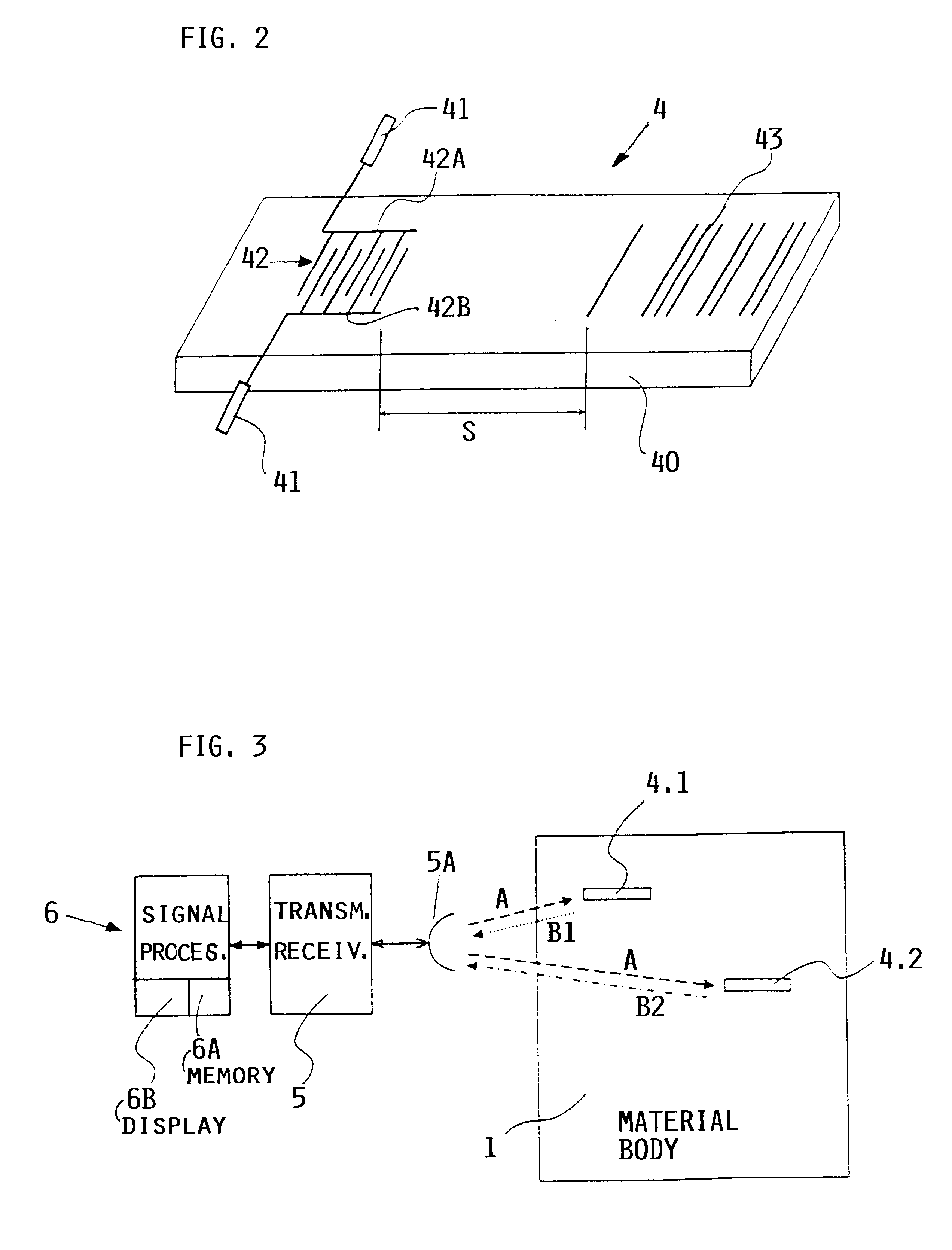
to provide a testing method that will yield information regarding existing defects and information regarding possible future defects; to provide an apparatus and method for testing different material characteristics, including temperature, modulus of shear, compression, density, and so forth; and to make it possible to perform the transmission of testing signals and reception of test information carrying signals in a wireless manner and without physical contact to provide a non-destructive testing.
By integrating or embedding a sensor with an antenna or a plurality of sensors with antennas forming a sensor system into the material, a constantly uniform consistent and optimal coupling of the sensor or sensors to the material is achieved, since the sensor with its antennas or sensors with their antennas become permanent components of the material such as a fiber composite material. Thus, a comparing and evaluation of different testing results obtained at different times from the material and / or from the adhesive bonding in the material becomes possible.
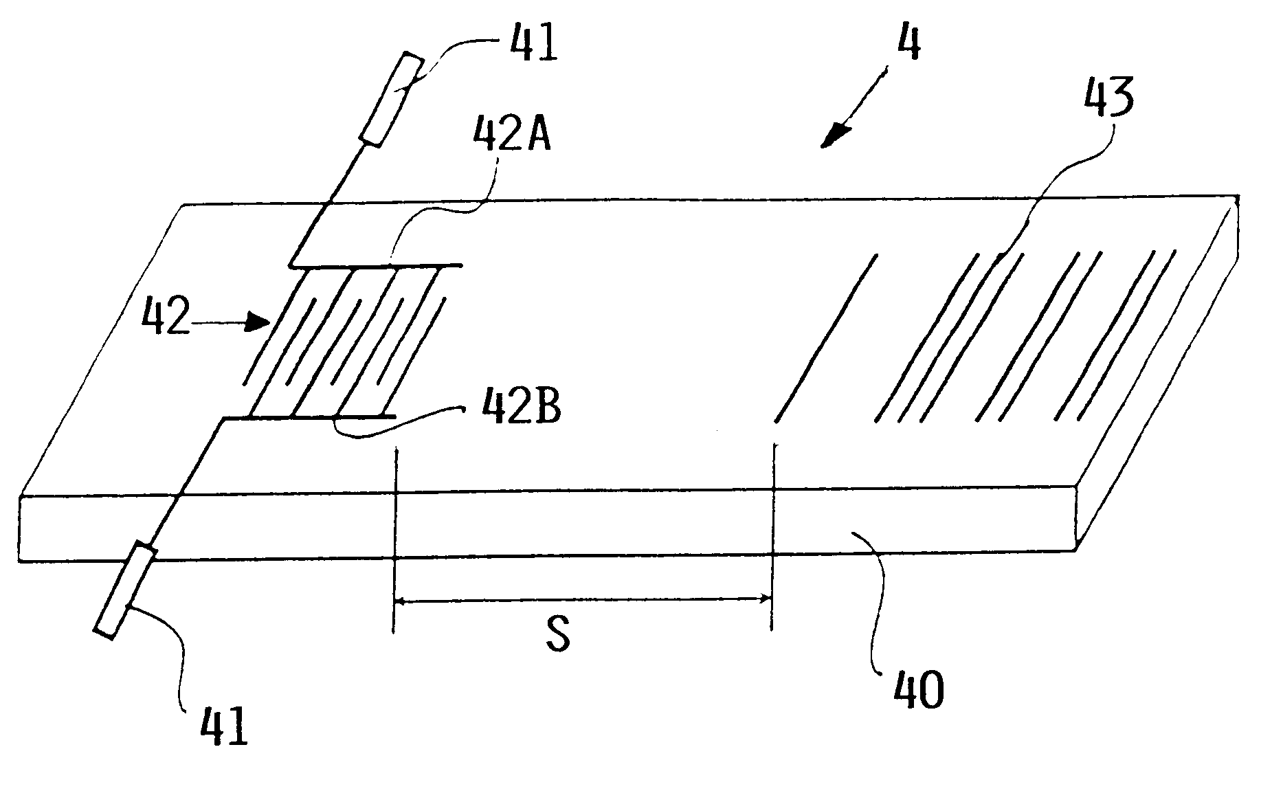
According to a further aspect of the invention, the present method of manufacturing a material that is testable in accordance with the teachings of the invention, especially fiber composite materials, introduces the sensors into the material, preferably prior to solidification, whereby these sensors have the above described receiver / transmitter characteristics. The transmitter returns a signal that depends on the status and / or quality of the material after it has solidified. Such an introduction of the sensors provides for an efficient and cost effective manufacture of the material or structural component made of such material, whereby the current status can be tested and judged externally at any time so that any defect or any beginning material changes can be localized. As mentioned, it is advantageous to use sensors that are SAW filters which are uniformly and / or randomly distributed in the material, whereby each sensor is preferably provided with its own identification code as mentioned.
The present method permits a rapid material testing without any substantial effort and expense, whereby the testing is neither invasive nor destructive. Sequentially repeated test results can be compared for an early defect recognition or for determining of structural changes signifying an impending defect because due to the uniform and solid bonding of the sensors to the material a consistent coupling is assured between the sensors and the material. Hence, different test results from tests made at different times are due to changes in the material and not due to inconsistent couplings between material and sensors.

Problems solved by technology

However, under high load conditions or under prolonged duration load conditions, such structural components may suffer structural damage within the volume of the material or structural component.
Thus, it is a disadvantage of polymer materials that such structural damage generally cannot be ascertained by mere external visual inspection.
For example, damages may be caused on an aircraft by impacts with a flying object such as impacts by birds.
Such damages are hard to detect or may not be detected at all, whereby high risks are involved.
However, many of the conventional methods fail where structures are involved having complicated configurations or else an enormous effort and expense is involved in the measuring of the data, for example where it becomes necessary to use temperature controlled testing chambers.
Another disadvantage of conventional methods is seen in that an evaluation by comparing identical or repeated measuring results is hardly possible because identical coupling conditions which are required for a comparing evaluation are hardly realizable.
Another drawback is seen in that in conventional methods only an existing failure can be detected, while an early recognition of possible or impending failures is not possible.
Furthermore, many of the known testing methods are not applicable for materials involving adhesive bonding or the adhesive materials themselves, because the required coupling conditions are not realizable with conventional methods.
Such materials require a high effort and expense for their manufacture and for the performance of the testing.
Yet, a precise localization of a defect is hardly possible or possible only with great effort and expense.

Method used


Image

  • System and method for material testing, material suitable for such testing and method for producing such material
  • System and method for material testing, material suitable for such testing and method for producing such material
  • System and method for material testing, material suitable for such testing and method for producing such material

Examples


Embodiment Construction

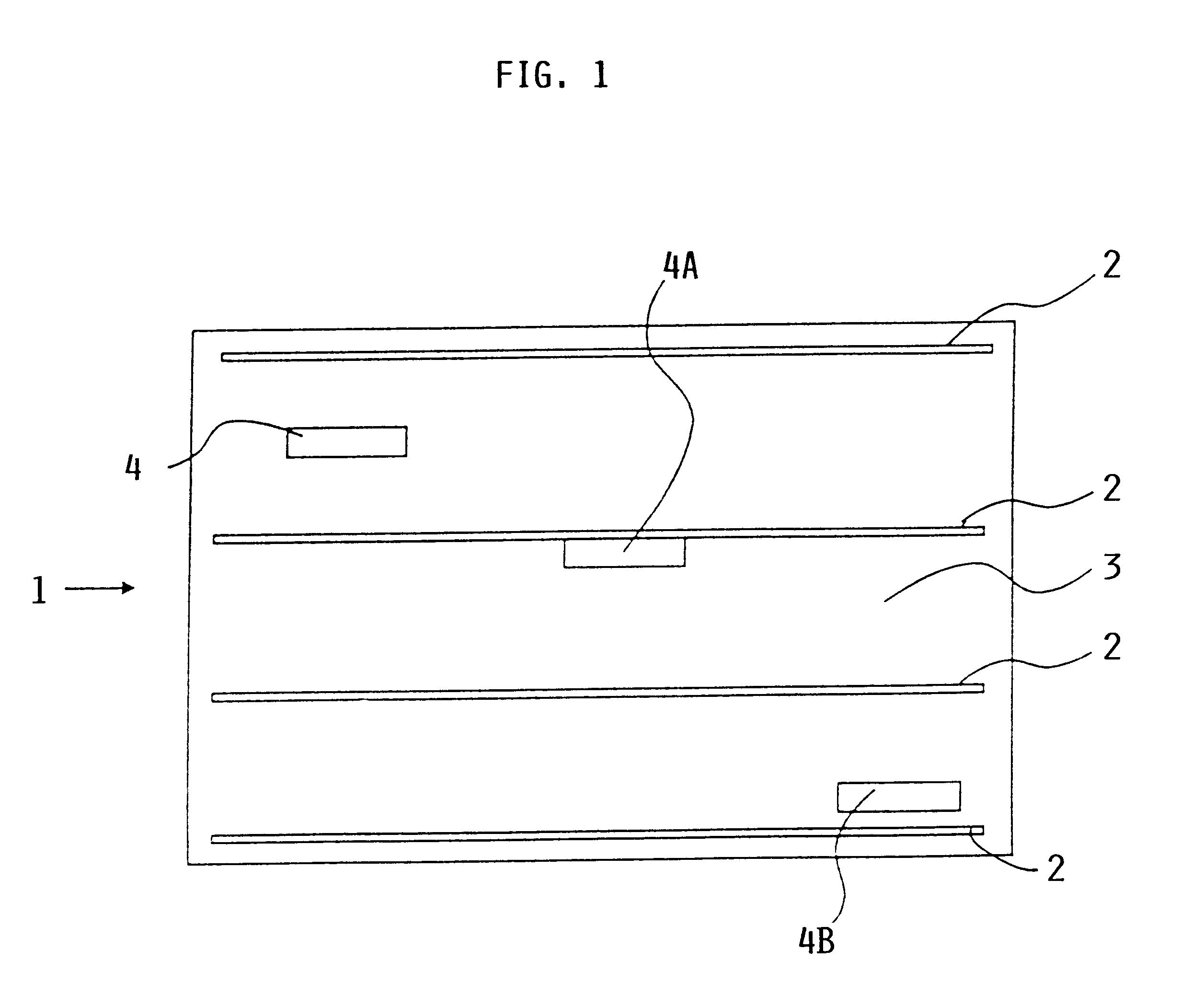
FIG. 1 shows schematically a view into a material body made of a fiber composite material 1. Fibers 2 are embedded in a matrix material 3 such as a resin or a filler material. Sensors 4 are embedded in the fiber composite material. The sensors 4 are transducers capable of functioning as signal receivers for receiving an excitation or testing signal and as signal transmitters for returning a material quality signal in response to an excitation signal and in accordance with the material qualities. The transmission of testing signals and the return transmission of material quality signals takes place in a wireless manner. Piezoelectric elements are suitable for this purpose. Piezoelectric materials suitable for the purposes of the invention are, for example, lithium niobate (LiNbO.sub.3), lithium tantalate (LiTaO.sub.3), STX quartz, and piezoelectric polymers. The sensors 4 are embedded so as to be entirely surrounded by and intimately bonded to the matrix material 3. A sensor 4A is em...


PUM


Abstract

A material, such as a fiber composite material, has embedded inside at least one, preferably more, surface acoustic wave filters of piezoelectric material for receiving testing energy in a wireless manner and for retransmitting a material quality signal in a wireless manner which is evaluated in a system that has a wireless transmitter for sending testing energy into a material and a wireless receiver for receiving the material quality signal which is then processed and evaluated by a respective processor of the testing system. An output of the processor provides information regarding the nature and quality of the material tested and of the presence and location of any material faults that may be displayed on display screen.

Description

PRIORITY CLAIMThis application is based on and claims the priority under 35 U.S.C. .sctn.119 of German Patent Application 198 05 584.6, filed on Feb. 12, 1998, the entire disclosure of which is incorporated herein by reference.The invention relates to a system and a method for material testing. The invention also relates to a material suitable for such testing, particularly fiber composite materials, adhesives, polymer materials, elastomer materials, thermoplastic and thermosetting materials, and to a method for producing such materials.BACKGROUND INFORMATIONPolymer materials, such as fiber composite materials and structural adhesives, are increasingly used in high stress structures and other structural components due to the stiffness of these materials combined with a relatively low weight or density. However, under high load conditions or under prolonged duration load conditions, such structural components may suffer structural damage within the volume of the material or structura...

Claims


Application Information

Patent Timeline
IPC IPC(8): G01N29/04G01D5/48
CPCG01D5/48G01N29/043G01N29/2475G01N2291/0289G01N2291/0235G01N2291/0258
Inventor GOEBEL, JOHANNMITTELBACH, ANDREAS
Owner DAIMLER AG
Learn More