However, in comparison with the location adjacent the
exhaust manifold, the position of the
exhaust pipe downstream from the
catalytic converter is likely to be subjected to water, thereby increasing a chance that water is introduced into a space inside the sensor.
The arrangement of the air fuel ratio sensor at the location downstream from the
catalytic converter likely causes the sensor to be subjected to splashing with water by the rotating wheels of the vehicle, thereby causing the water to be introduced into the space inside the sensor.
This causes the output level of the sensor to be reduced and causes a crack to be generated in a detecting element, resulting in damage in the sensor.
The crimping of the cover after fitting the rubber seal with the lead wires causes a resulting compression force to be concentrated at the thin portion, thereby generating a
large deformation.
In this case, a sealing capacity is worsened between the lead wires and the corresponding holes, thereby reducing its waterproofness.
Finally, under the recent trend of the location of the air fuel ratio at an environment of an increased temperature and of an increased chance of to an
exposure to water, the structure of the air fuel ratio sensor in the prior art likely causes the waterproofness to be easily worsened.
Thus, the simultaneous crimping operation may cause a desired crimped condition not to be obtained for both of the
metal part and the rubber part.
Namely, even if the crimping of the outer cover is desirably done, the undesirable crimped condition at the rubber seal member causes a water to leak via the gap between the
rubber material and the inner cover.
Contrary to this, if the rubber member is overly subjected to the crimping, it causes a crack to be generated in the
rubber material.
In this connection, an insufficient crimping implies a situation that the force during the crimping is not enough so that a deformation of the outer cover is smaller than a desired value.
Contrary to this, an excessive crimping implies a situation that the force during the crimping is excessive so that a deformation of the outer cover is larger than a desired value.
Contrary to this, even if a desired crimped condition is obtained in the rubber seal member, an insufficient crimping of the outer cover to the inner cover may generate a situation that a water is leaked via the gap between the covers.
Furthermore, if an excessive crimping is occurred between the inner and outer cover, a situation may occur that a crack is generated in the cover, which causes the material to be easily eroded.
In this case, the durability of the crimped portion between the inner and outer cover is insufficient to
resist a vibration, which may cause the crimped portion to be loosened.
This is disadvantageous in an arrangement of the air fuel ratio sensor at the location downstream from the
catalytic converter, since this location is likely subjected to splashing by water as well as to a large vibration during the running of the vehicle.
However, this increase a work for an
assembly of the sensor and a production cost is increased.
However, the size of the seal member is increased, which cause a production cost to be increaseddue to the increased use of the
rubber material.
Furthermore, the size of the air fuel ratio sensor as well as related parts are correspondingly increased, resulting in an increase in cost due to increased use of materials.
Furthermore, a productivity during an
assembly of the sensor is worsened.
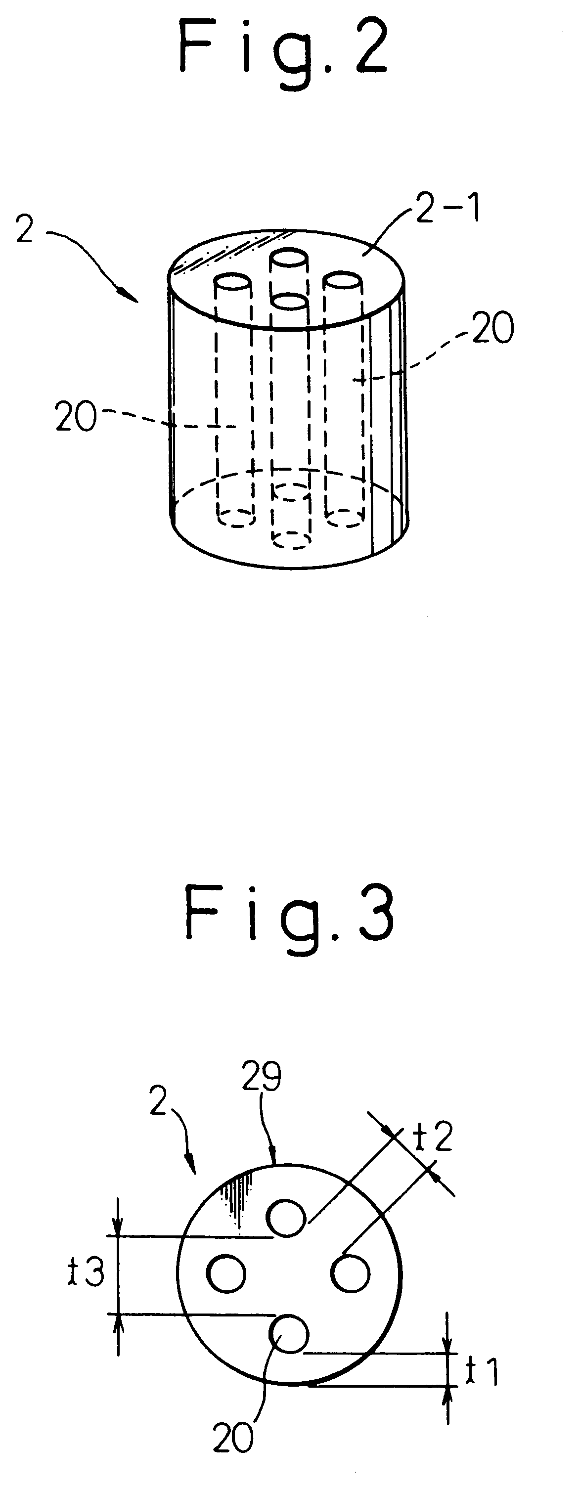
The deformation of the seal member smaller than 10% may cause the compression force to be insufficient in the seal member, which makes the seal to be insufficient between the lead wires and the corresponding holes.
Contrary to this, the deformation of the seal member larger than 20% may cause the compression force to be excessive in the seal member, resulting in a generation of a defects such as a crack in the seal member.
The rubber of the
hardness more than 85 Hs may cause the seal member to be less flexible, thereby making it difficult to obtain a desired contact with respect to the lead wires.
Otherwise, a construction for obtaining an electric insulation as well as for preventing the lead wires from being withdrawn would be complicated, resulting in an increase in work during an
assembly, causing the production cost to be increased.
The wall thickness of the inner cover smaller than 0.4 mm may cause the strength of the cover to be overly reduced, resulting in a possibility that a protection of parts by the cover can not be attained.
Contrary to this, the wall thickness of the inner cover larger than 0.8 mm may causes the crimping to become difficult due to an increased crimping force.
Furthermore, a generation of
erosion is likely due to a crack generated by the force in the crimping during the use of the sensor.
The wall thickness of the outer cover smaller than 0.3 mm may cause the strength of the cover to be overly reduced, so that the cover is easily deformed and it may possible that a
stable fixation of the outer cover to the inner cover can not be obtained.
The wall thickness of the inner cover larger than 0.6 mm may causes the crimping to become difficult.
Contrary to this, the crimping at six position may cause the spacing between the pressers to be excessively long in the circumferencial direction, resulting in an uneven crimping in the circumferential directions, resulting in an insufficient sealing at the crimped portions.
Finally, a crimping at seven positions will be impractical from the view point of a design of the apparatus.
Furthermore, a crimping at points of nine or more makes the number of working steps during the crimping to increase due to the increased number of pressers, which requires an extra labor cost.
Thus, the large crimping force at the first section, which is still continued, causes the inner and outer covers to be relatively moved in a direction parallel to the axis of the sensor or in a rotating direction about the same axis, resulting in the sealing to be worsened between the
water repellent seal and the inner and outer covers.
A
hardness of the inner cover smaller than 150 cause the difference with respect to the
hardness of the outer cover to be excessively small, which causes the condition of the crimping to be worsened.
Furthermore, the inner cover is likely to be deformed, which prevent the body of the sensor from being desirably protected.
Contrary to this, a degree of the hardness of the inner cover larger than 400 can cause a crack to be generated during working.
Furthermore, a stress
erosion crack can be generated during use after the fixation.
The degree of the hardness of the outer cover larger than 300 causes the difference thereof to be insufficient with respect to the degree of the hardness of the inner cover, which causes the crimping to be difficult, thereby causing the fixation to be insufficient.
A thickness of the inner cover smaller than 0.4 mm causes its strength to be insufficient, resulting in deteriorating the designated function as the cover for protecting parts therein.
Contrary to this, a thickness of the inner cover larger than 0.8 mm causes the working to be difficult, and a stress
erosion crack can be generated during use after crimping.
The thickness of the inner cover smaller than 0.4 mm causes its strength to be insufficient, resulting in deteriorating the designated function as the cover for protecting parts therein.
A thickness of the outer cover smaller than 0.3 mm causes the strength to be insufficient, so that the deformation by an outer force is likely, and it is possible that the inner cover is not securely connected to the inner cover.
The thickness of the outer cover larger than 0.6 mm may cause the crimping to be difficult.
A thickness of the inner cover smaller than 0.4 mm causes its strength to be insufficient, resulting in deteriorating the designated function as the cover for protecting parts therein.
Contrary to this, a thickness of the inner cover larger than 0.8 mm causes the working to be difficult, and a stress erosion crack can be generated during use after crimping.
