Differential gear

a technology of differential case and gear plate, which is applied in the direction of gearing details, mechanical equipment, gearing, etc., can solve the problems of increasing the cost, and increasing so as to reduce the number of components (bolts), the effect of reducing the weight of the differential case and reducing the cos

Inactive Publication Date: 2012-05-29
MUSA PRECISION IND CO LTD
View PDF9 Cites 1 Cited by
  • Summary
  • Abstract
  • Description
  • Claims
  • Application Information

AI Technical Summary

Benefits of technology

[0008]The present invention has been made to solve the above problems. It is an object of the present invention to provide a differential gear having a desired durability, in which a first differential case and a second differential case are secured to each other not by means of bolts so as to reduce a weight, and the number of components are reduced so as to reduce a cost.
[0010]According to the present invention, since no bolt is required to secure the first differential case and the second differential case to each other, thicknesses of the first differential case and the second differential case can be reduced, to thereby reduce a weight of the differential case. Further, since the number of components (bolts) can be reduced, a cost reduction can be achieved. Furthermore, as the first differential case, a part on a side ranging from the pinion-shaft installation part to the ring gear (including the ring gear) is made of only a low-carbon steel containing less than 0.45% of C, and is integrally molded by forging. In addition, a welding part between the first differential case and the second differential case is located outside a torque transmission area (area between the pinion-shaft installation part and the ring gear). Therefore, the welding part that is poor in strength can be prevented from being damaged when a torque is transmitted. Moreover, since the first differential case containing less than 0.45% of C and the second differential case containing less than 0.45% of C are welded to each other, there is little possibility that the welding part hardens to generate a crack. Therefore, there can be provided the differential gear having a desired durability.
[0011]Preferably, the first differential case and the pinion shaft are secured to each other by caulking. This securing method is significantly simple. In particular, since the first differential case is integrally molded from only the low-carbon steel containing less than 0.45% of C, by forging or by forging and cutting, the first differential case has an excellent tenacity. Thus, when the pinion shaft is secured thereto by caulking, breakdown of the first differential case can be avoided. In this case, preferably, the pinion shaft is molded from only a low-carbon steel containing less than 0.45% of C. In this case, since the pinion shaft also has an excellent tenacity, when the pinion shaft is secured to the first differential case by caulking, breakdown of the pinion shaft can be avoided.
[0017]According to the present invention, since no bolt is required to secure the first differential case and the second differential case to each other, thicknesses of the first differential case and the second differential case can be reduced, to thereby reduce a weight of the differential case. Further, since the number of components (bolts) can be reduced, a cost reduction can be achieved. Furthermore, as the first differential case, a part on a side ranging from the pinion-shaft installation part to the ring gear (including the ring gear) is made of only a first structured steel containing less than 0.60% of Carbon Equivalent, and is integrally molded by forging, or forging and cutting. In addition, a welding part between the first differential case and the second differential case is located outside the torque transmission area (area between the pinion-shaft installation part and the ring gear). Therefore, the welding part that is poor in strength can be prevented from being damaged when a torque is transmitted. Moreover, since the first differential case made of the first structured steel containing less than 0.60% of Carbon Equivalent and the second differential case made of a second structured steel containing less than 0.60% of Carbon Equivalent are welded to each other, there is little possibility that the welding part hardens to generate a crack. Therefore, there can be provided the differential gear having a desired durability.

Problems solved by technology

This disadvantageously invites an increase in weight of the differential case.
In addition, since a plurality of bolts are required, there is a problem in that the number of components is increased, which results in cost increase.
However, since a welding part between the first differential case and the second differential case, and a welding part between the second differential case and the ring gear, are located in an area through which a driving force from an engine is transmitted (an area between the pinion-shaft installation part and the ring gear), there is a possibility that the welding parts, which are relatively poor in strength, are cracked when a torque is transmitted.
Namely, the differential case has a durability problem.

Method used


Image

  • Differential gear
  • Differential gear
  • Differential gear

Examples


Embodiment Construction

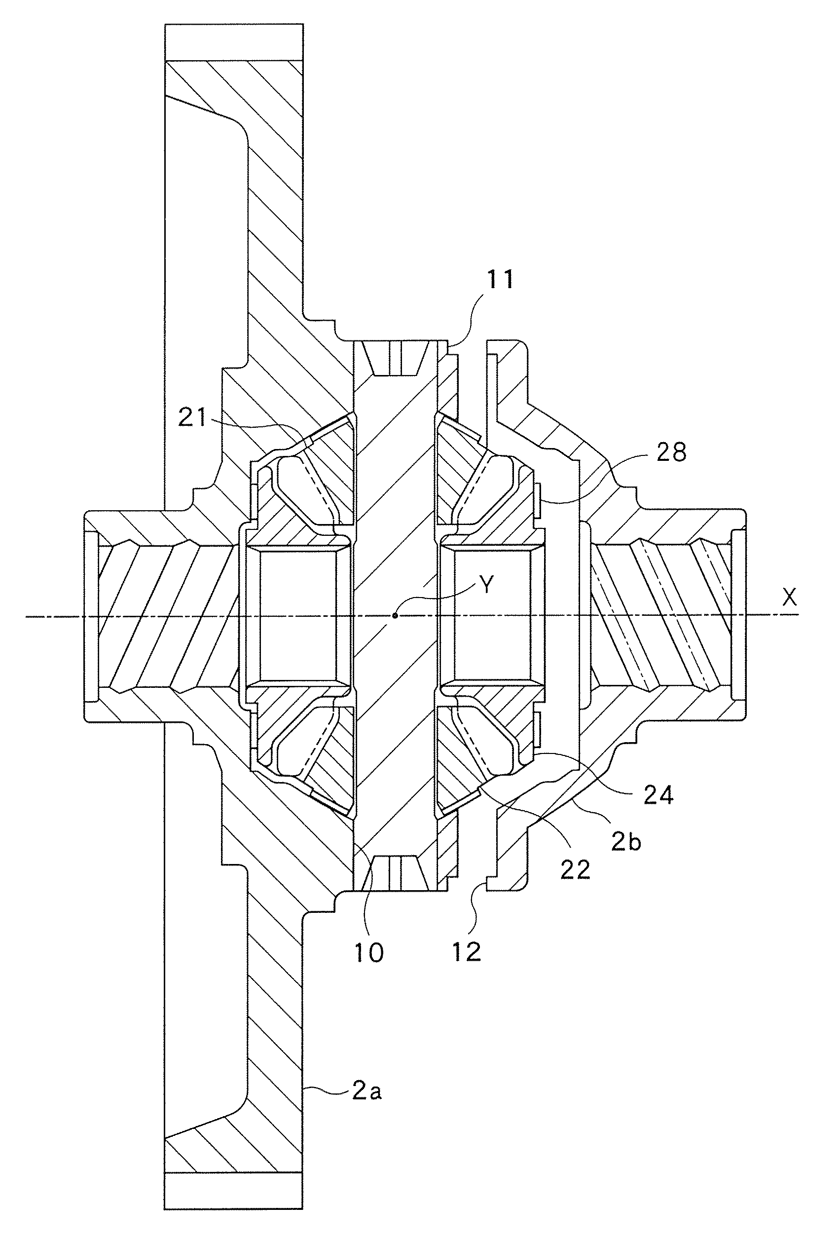
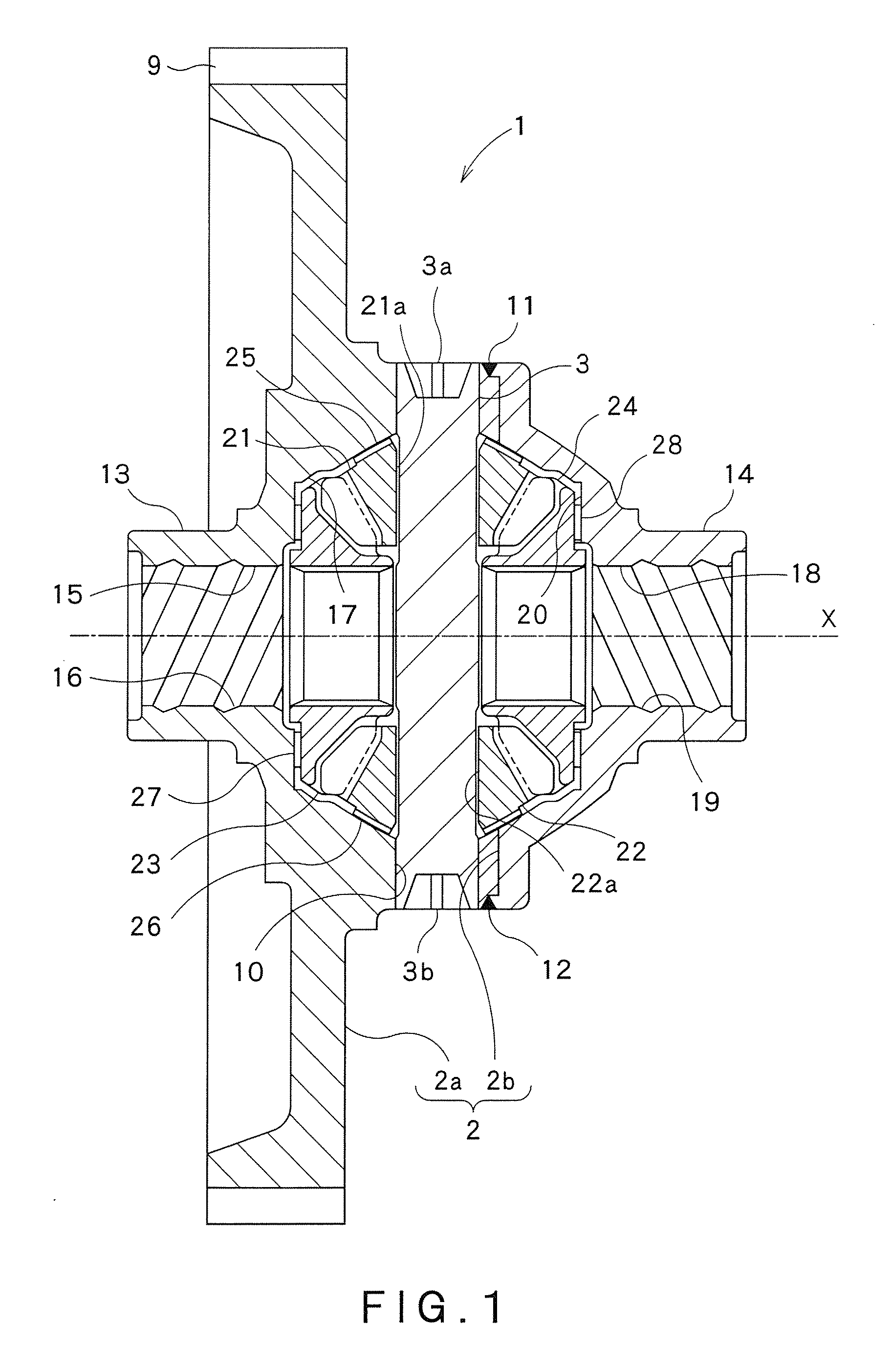
[0036]FIG. 1 is a sectional view of a differential gear in one embodiment of the present invention.

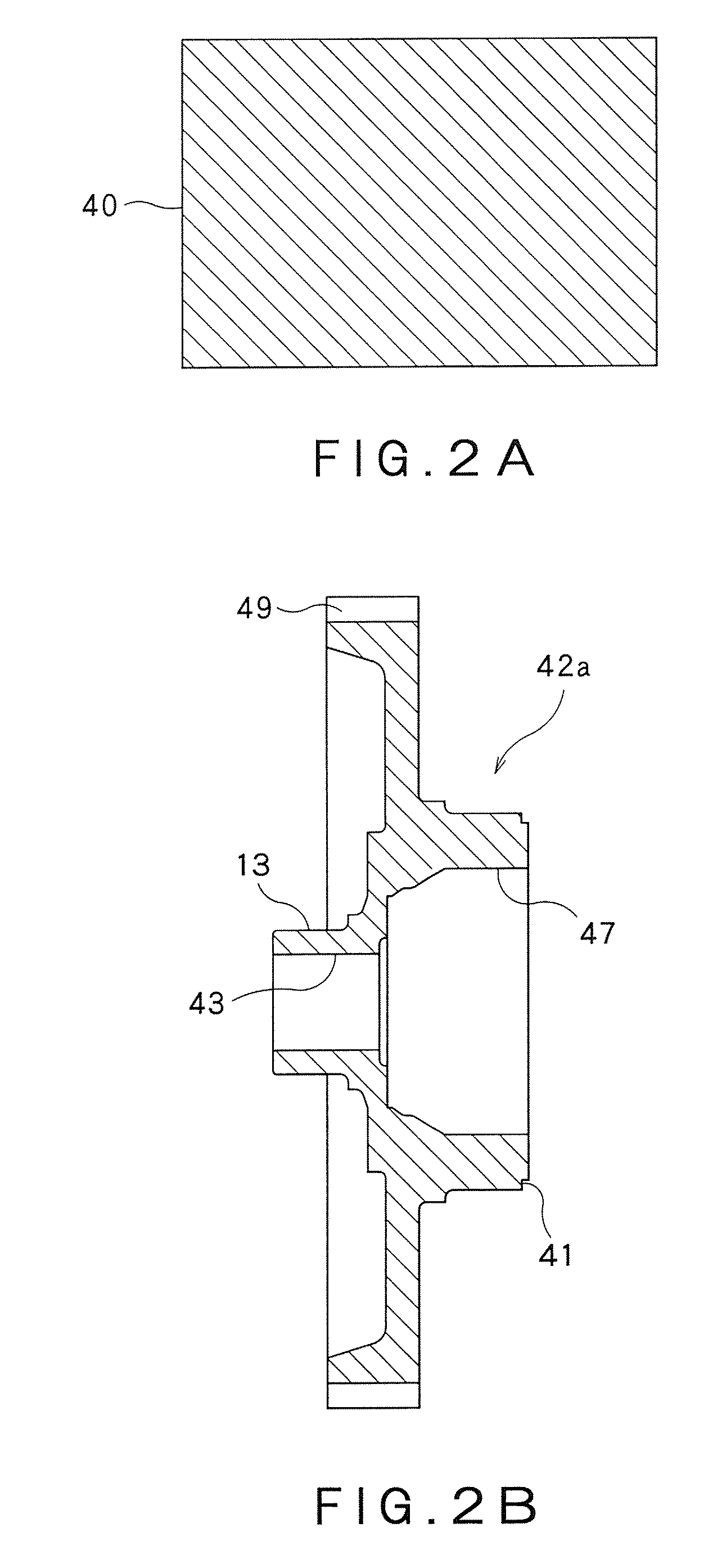
[0037]FIG. 2A is a sectional view of a first material, for explaining a molding step of a first differential case of the differential gear in one embodiment of the present invention. FIG. 2B is a sectional view of a preparatory first differential case, for explaining the molding step of the first differential case of the differential gear in one embodiment of the present invention. FIG. 3 is a sectional view of the first differential case of the differential gear in one embodiment of the present invention. FIG. 4A is a sectional view of a second material, for explaining a molding step of a second differential case of the differential gear in one embodiment of the present invention.

[0038]FIG. 4B is a sectional view of a preparatory second differential case, for explaining the molding step of the second differential case of the differential gear in one embodiment of the present invention...


PUM


Abstract

In a differential gear, a differential case includes: a first differential case on a side ranging from a pinion-shaft installation part on which a pinion shaft is installed, to a ring gear; and a second differential case on a side opposite to the side ranging from a pinion-shaft installation part on which the pinion shaft is installed, to the ring gear. The first differential case is integrally molded from only a low-carbon steel containing less than 0.45% of C, by forging or by forging and cutting. The second differential case is integrally molded from only a low-carbon steel containing less than 0.45% of C, by forging or by forging and cutting. The first differential case and the second differential case are bonded to each other by welding.

Description

CROSS REFERENCE TO RELATED APPLICATIONS[0001]This application is based upon and claims the benefit of priority from the prior Japanese Patent Application Nos. 2007-254519 filed on Sep. 28, 2007, and 2008-242389 filed on Sep. 22, 2008, the entire contents of which are incorporated herein by reference.FIELD OF THE INVENTION[0002]The present invention relates to a differential gear including: a ring gear to which a driving force is inputted from a driving source so as to be rotated; a differential case configured to be rotated together with the ring gear; a pinion shaft installed on the differential case, the pinion shaft being configured to be rotated together with the differential case; pinion gears pivotally mounted on the pinion shaft; and side gears configured to be meshed with the pinion gears.BACKGROUND ART[0003]There has been conventionally known a differential gear used in a vehicle such as an automobile, which transmits a driving force (torque) from an engine, through a ring ...

Claims


Application Information

Patent Timeline
Patent Type & Authority Patents(United States)
IPC IPC(8): F16H48/06
CPCF16H48/08F16H48/40Y10T74/2186F16H2048/382F16H2048/385F16H2048/085
Inventor FUJITA, TOMOYUKIMATAGA, AKIRA
Owner MUSA PRECISION IND CO LTD
Why Eureka
Try Eureka