
Device for protecting selective cutting machines against overload

a cutting machine and overload technology, applied in the direction of slitting machines, earthwork drilling and mining, etc., can solve the problems of inability to detect stress correctly by vibration sensors, severe vibration, and breakage of parts and especially of cutters

Inactive Publication Date: 2001-07-10
VOEST ALPINE BERGTECHNIK GMBH
View PDF7 Cites 9 Cited by
  • Summary
  • Abstract
  • Description
  • Claims
  • Application Information

AI Technical Summary

Benefits of technology

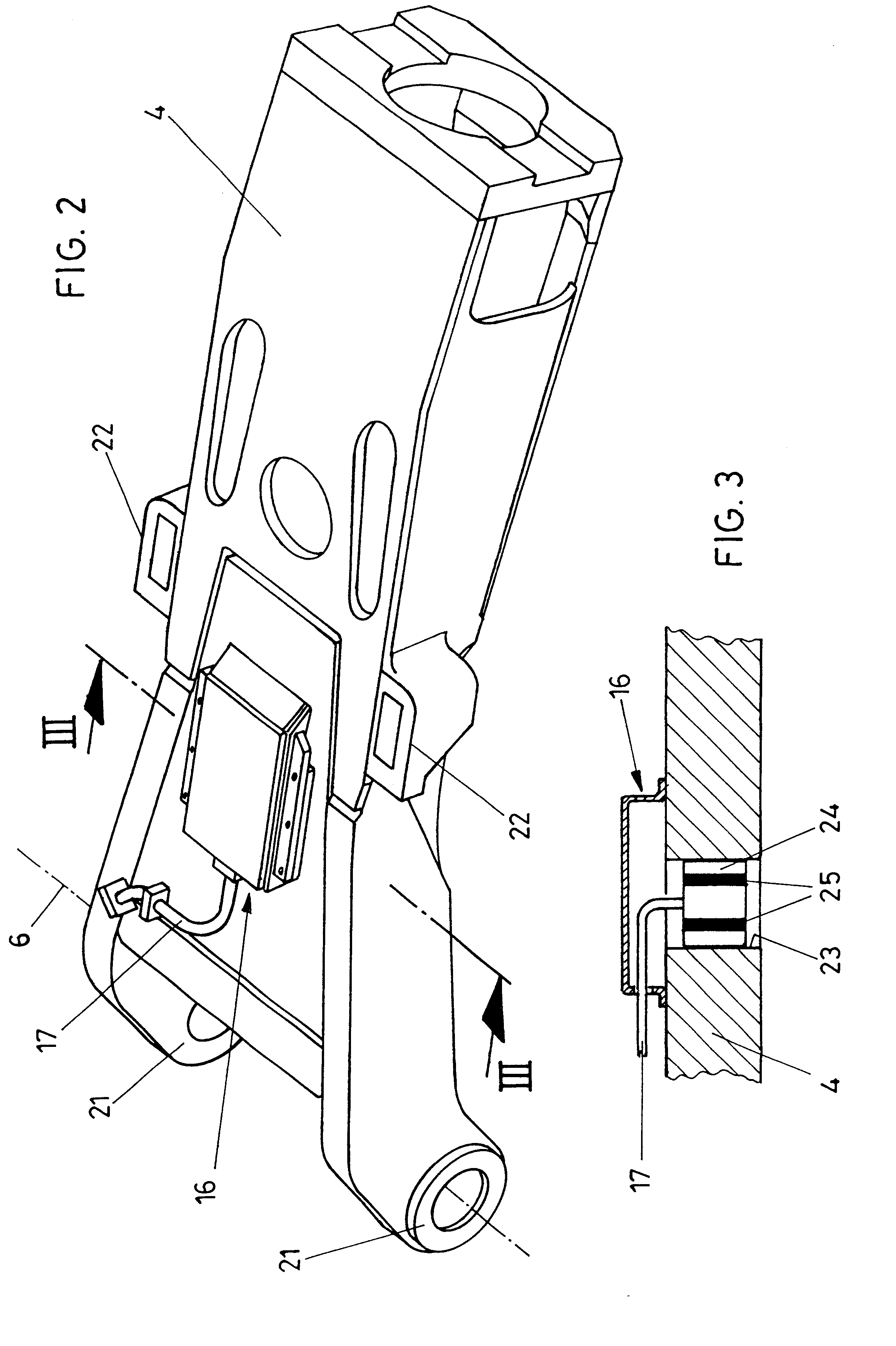
An especially reliable detection of impermissible forces and thus a reliable detection of any possible overload can be attained in that the sensor is disposed in or on a housing wall of the cantilevered arm.
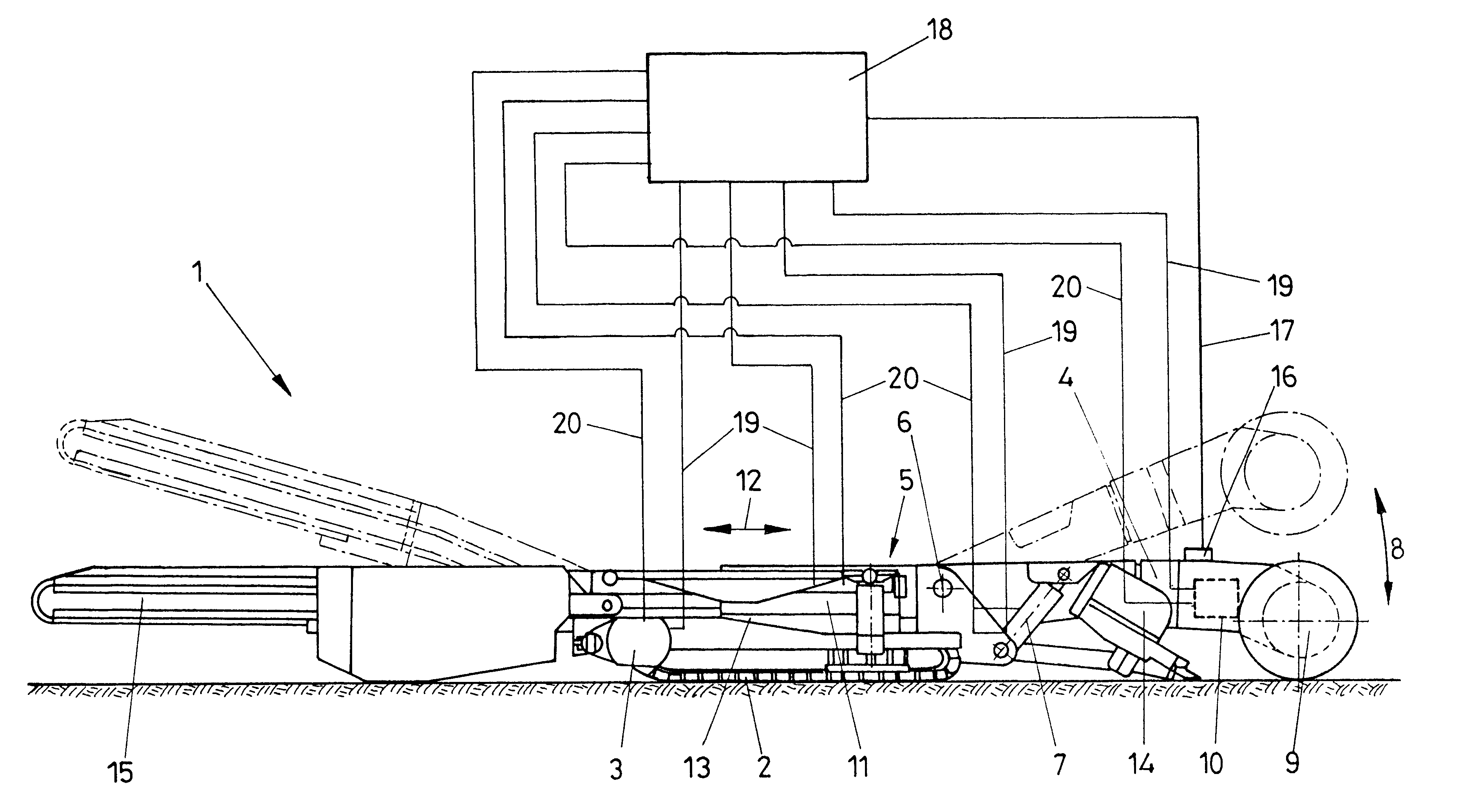
For various operating states, the procedure is advantageously such that the evaluation circuit, in penetration cutting, generates control signals for the drive mechanism of the cutter motor and the displacement drive mechanism, in particular the hydraulic displacement cylinder for the bearing of the pivot axis of a roller cutting machine, or that the evaluation circuit in cutting by a roller cutting device in the vertical direction (shearing), generates control signals for the drive mechanism of the cutter motor and for the pivot cylinder for the vertical pivoting of the cantilevered arm, or that when curves are being cut, control signals for the track-type running gear drive mechanism are generated in addition to the control signals for the cutter motor and the vertical pivoting cylinder. These special operating states, such as penetration cutting, so-called shearing, or curve cutting, can in this way be mastered reliably with only slight corrections and without the possibility of an overload.
Especially reliable detection and correspondingly clear signals of the strain or deformation measuring sensors can be obtained in that the sensor or sensors on the cantilevered arm are disposed closer to the pivot axis of the cantilevered arm and preferably in the one-third of the length of the cantilevered arm adjacent to the pivot axis; this arm is embodied as a box profile frame. In an especially simple way, the embodiment is such that the deformation sensors are embodied as strain measuring sensors or strain gauges fixed to a thin-walled carrier and the carrier plate is fixed to the outside of the cantilevered arm.

Problems solved by technology

Any deviation in pivoting speed from the pivoting speed for which the arrangement of cutters on the cutting head was designed can lead to severe vibrations, which can lead to the breakage of parts and especially of the cutters.
However, above all in roller cutting machines, impermissible stresses and overloads are of particular importance, and such stresses cannot be detected correctly by vibration sensors.
When materials are being worked, it often happens that regions of less hardness or toughness or that are highly brittle are penetrated, and in these regions even large pivoting angles of the cutting arm have still not led to excessive loads, because the material can readily be cut or broken.
However, if in certain pivoted positions a higher pressure resistance to a test cube is exerted on material, the result is impermissible stresses, which can cause heavy damage to the machine.
Such devices are relatively complicated and expensive, because they have to be disposed in the immediate vicinity of the cutters acted upon by the cutting pressure, and the bearing points for pivoting the cutters are subject to correspondingly high wear.

Method used


Image

  • Device for protecting selective cutting machines against overload
  • Device for protecting selective cutting machines against overload
  • Device for protecting selective cutting machines against overload

Examples


Embodiment Construction

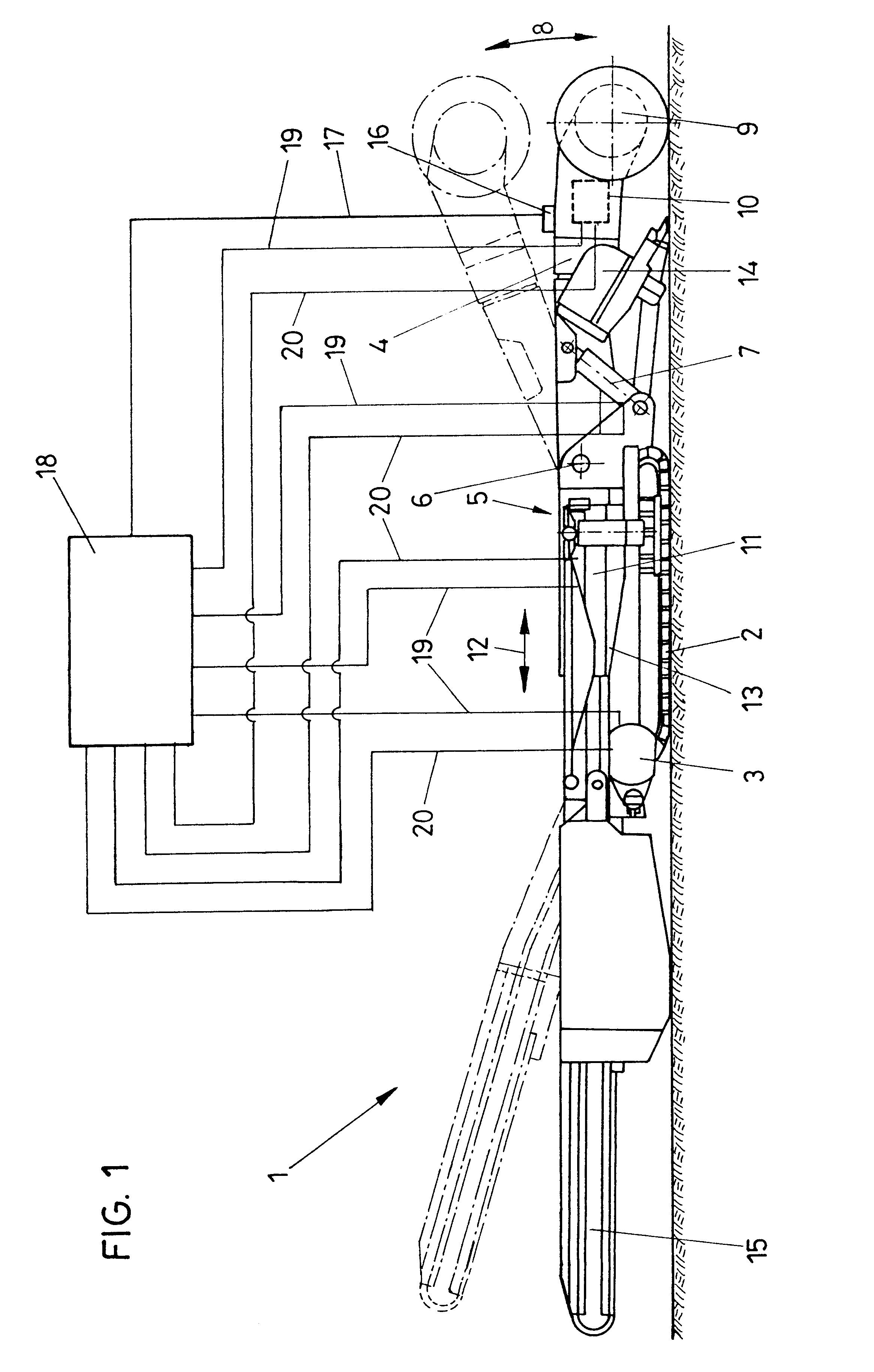
In FIG. 1, a roller cutting machine 1 is shown, which can travel on a track-type running gear 2; the drive mechanism of the track-type running gear is designated by reference numeral 3.

A cantilevered arm 4 is pivotably supported vertically on a carriage 5 about a substantially horizontal axis 6. The pivot drive mechanism for this vertical pivoting about the pivot axis 6 is designated by reference numeral 7 and is formed by a hydraulic cylinder-piston unit that is pivotably connected to the cutting arm 4. The cutting arm 4 carries rotatably supported cutting rollers 9. As the cutting drive mechanism 10 for the cutting rollers 9, a cutter motor is provided, disposed in the cantilevered arm 4. The carriage 5 is displaceable, via a displacement drive mechanism 11 embodied as a cylinder-piston unit, in the direction of the double arrow 12. On the machine frame 13, a loading device 14 and a discharge device 15 are also provided. On the cantilevered arm 4, there is also a strain or deforma...


PUM


Abstract

The invention relates to a device for protecting selective cutting machines against overload, in which the selective cutting machine has cutting tools, in particular cutting rollers, rotatably supported on a pivotable cantilevered arm, and both the cutting tools and the cutting arm are connected to separate drive mechanisms. At least one strain or deformation measuring sensor is disposed on the pivotable cantilevered arm, and its signals are delivered to an evaluation circuit; the evaluation circuit is connected via control lines at least to the drive mechanisms of the cutting arm and the cutting tool.

Description

1. Field of the InventionThe invention relates to a device for protecting selective cutting machines against overload, in which the selective cutting machine has cutting tools, in particular cutting rollers, rotatably supported on a pivotable cantilevered arm, and the cutting tools and the cutting arm are connected to separate drive mechanisms.2. Prior ArtSelective cutting machines, having cantilevered arms that are pivotable about at least two axes, as a rule have either cutting heads or cutting rollers. In the case of cutting heads, such cutting heads are usually designed for a particular pivoting speed of the cutting arm, so as to obtain a correct cutting pattern for a predetermined pressure resistance of a test cube on the part of the rock to be worked. Any deviation in pivoting speed from the pivoting speed for which the arrangement of cutters on the cutting head was designed can lead to severe vibrations, which can lead to the breakage of parts and especially of the cutters. S...

Claims


Application Information

Patent Timeline
Patent Type & Authority Patents(United States)
IPC IPC(8): E21C27/24E21C27/00E21C35/00E21C35/04
CPCE21C35/043E21C27/24
Inventor SIEBENHOFER, GOTTFRIEDLEITNER, WALTERSIFFERLINGER, NIKOLAUS
Owner VOEST ALPINE BERGTECHNIK GMBH
Learn More