
Binder assembly system employing an integral, book-like cover and adhesive channel

Inactive Publication Date: 2001-06-26
GWYN BRUCE A +1
View PDF4 Cites 40 Cited by
  • Summary
  • Abstract
  • Description
  • Claims
  • Application Information

AI Technical Summary

Benefits of technology

A primary goal of the present invention preferably is to create a flexible channel in a flat cover, that is, a cover that lies flat when put exterior-down on a supporting surface without the use of any internal or external, metal spine member. The cover of the invention includes a centrally located, longitudinally extended channel into which the pages to be bound are placed, flanked by two, side covers, a back cover and a front cover, with the three elements being integrated together into a single, "hard-bound" book-like item or piece. The joining areas between the side covers and the channel spine are very flexible, allowing the side covers to lie essentially flat or lie down on a supporting surface.
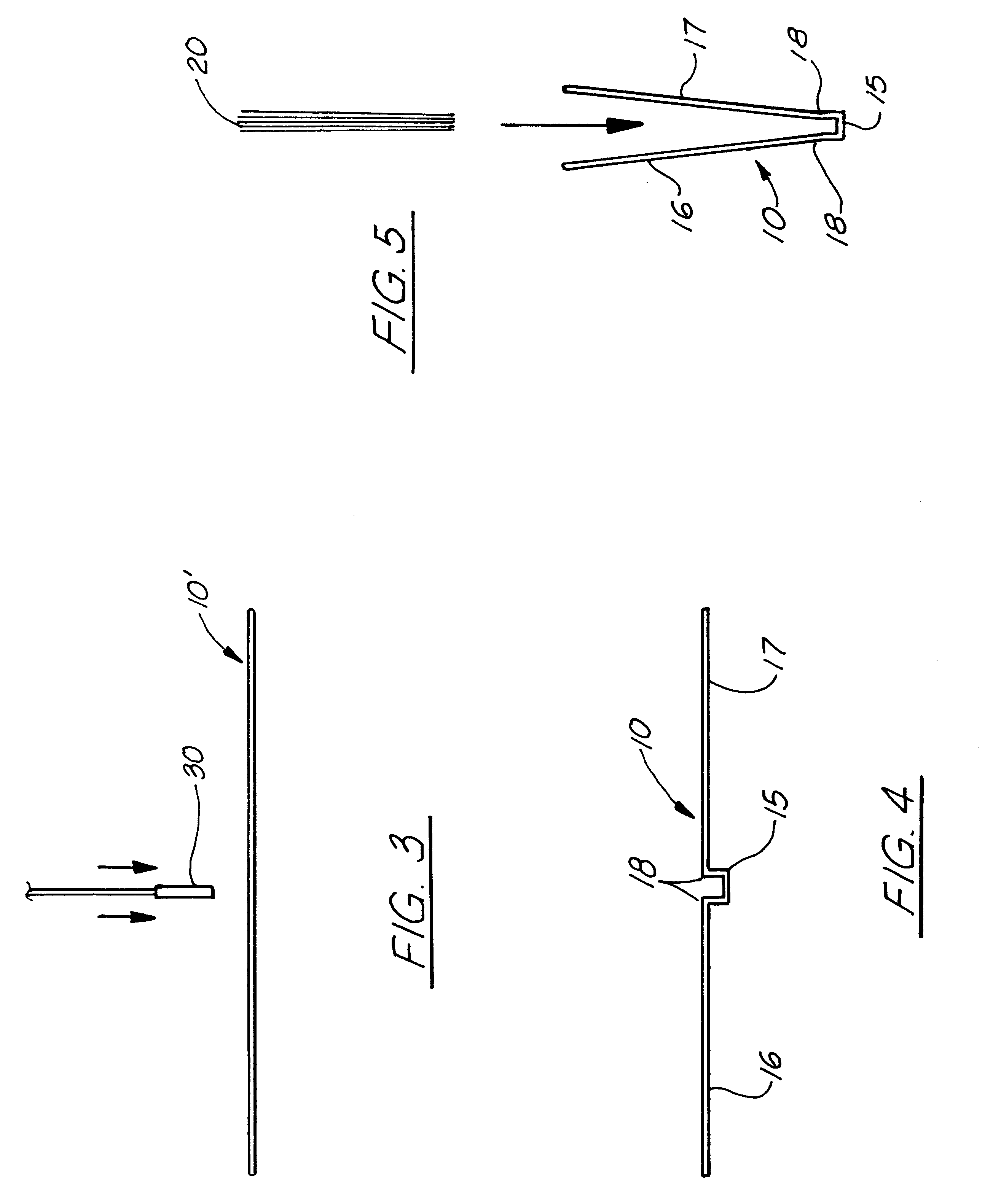
FIG. 5 is an end view of the finished, "hard-bound" book-like, binder cover, being used by the end-user to bind the exemplary sheet materials which are being inserted down (note direction arrow) into the interior of the exemplary embodiment of the finished, binder cover of the invention, which, after complete insertion and assembly of the sheet material into the cover, typically will then be inserted into the slot of a heating unit for heating the adhesive in the interior of the binding spine channel, causing it to flow and bind all of the individual sheets of material to the cover when it cools.

Problems solved by technology

In such an arrangement, it is difficult to place uniformly all the sheets into the U-shaped profile, especially when dealing with thick bundles.
Problems persist in the prior art which have not been successfully addressed.
Meanwhile, new challenges have surfaced from recent improvements.
The primary problem with the use of a metal element for the spine or heat-conducting element, arises when the spine is subject to certain bending loads and other external loads and strain present during shipping, handling and use.
The stiff, inflexible metal element, and thus the spine, has a tendency to become and stay crimped, thereby mis-aligning the sheet materials, and further inducing excessive wear.
It also difficult for a book or bound collection of sheet materials to remain open at certain pages when laid down.
This is not only unattractive and burdensome, but it also creates an unprofessional appearance to the bound report, product catalog, etc.
Another undesirable aspect of the metal spine is that it generally appears dull and uninviting.
Although the present invention uses an aesthetically pleasing cover, this prior art approach, however, significantly compromises the simplicity in the manufacture and application of the binding assembly and adds far more complexity to the manufacturing process.
Another problem persistent in known adhesive binding assemblies is related to the use of overly large quantities of hot-melt glue for the heating and binding operation, with such large quantities being added apparently to ensure adhesion, with the glue typically being overly added in a long, continuous strip of a relatively great thickness.
However, not to mention the cost of such an excessive amount of glue or adhesive, during the heating step, the adhesive glue has the tendency to flow up and around, not only the edges of the sheet materials to be bound, but beyond the binding areas and onto exposed areas of the sheet materials, covers or upper edges of the channel spine.

Method used


Image

  • Binder assembly system employing an integral, book-like cover and adhesive channel
  • Binder assembly system employing an integral, book-like cover and adhesive channel
  • Binder assembly system employing an integral, book-like cover and adhesive channel

Examples


Embodiment Construction

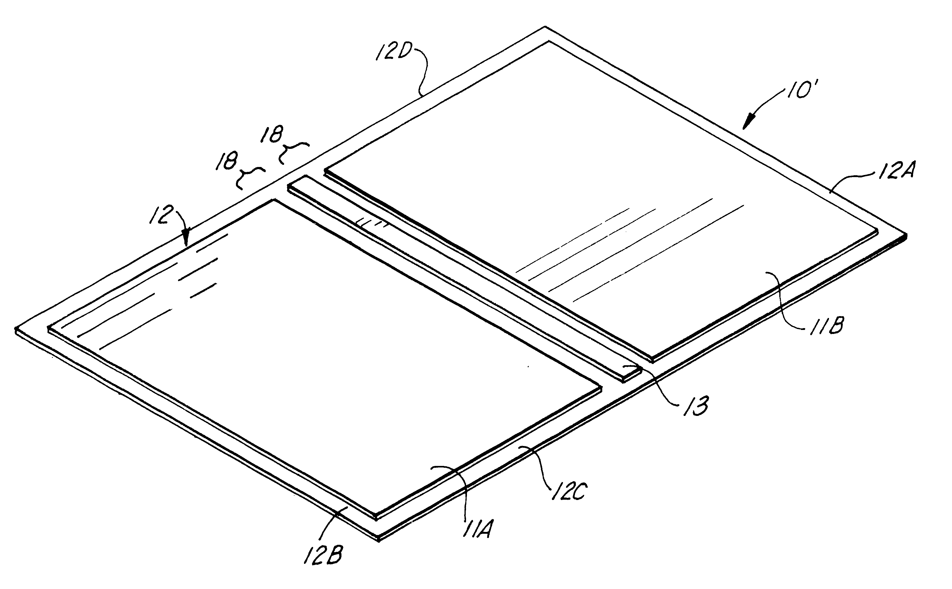
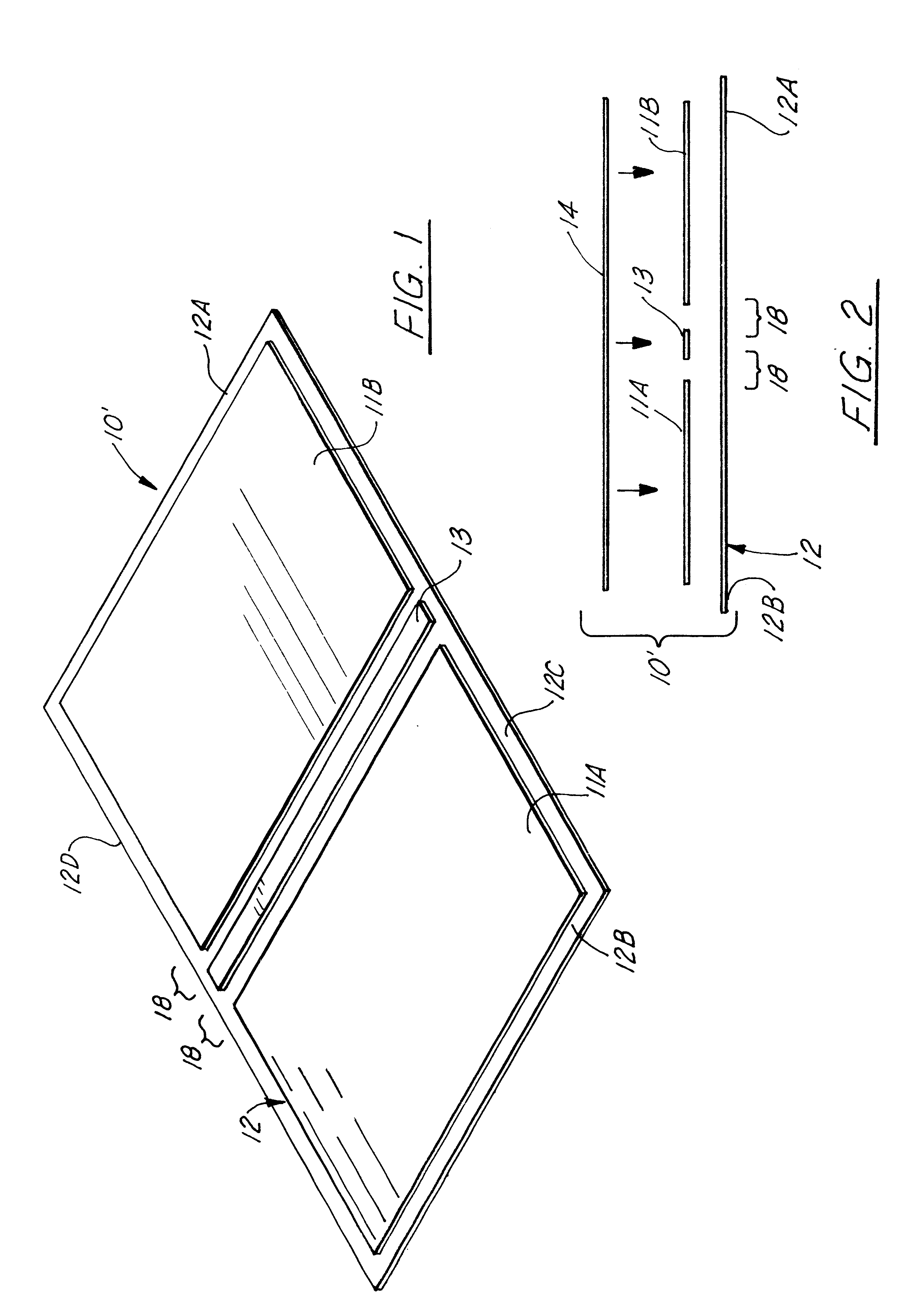
As can be seen in FIGS. 1 & 2, the exemplary embodiment of the "hard-bound" book-like, binder cover 10' (in its final form numbered 10) of the invention includes a number of main, structural parts, including two, side boards 11A & 11B, an exterior sheet 12 of book covering material and, optionally, a centrally located, special paper spine element 13, used to make up the final "hard-bound" book-like, binding cover 10. As can be seen in FIG. 1, the sides of the paper spine element 13 are positioned adjacent to but spaced from the sides of the boards 11A & 11B, the three parts being positioned in a parallel array symmetrical about the center-line axis of the paper spine element. A final part is the typically decorative, internal, paper cover 14, which can have a plain exposed side and which over-lies and covers over the combined width of the side boards 11A & 11B and the paper spine element 13, all of which when combined together form the final binder cover 10 in pre-heating and formin...


PUM


Abstract

A binder assembly system, without a metal spine but only paper or paper-like material at its channel spine (15), for binding together a series of sheet materials (20), using an "hard cover" book-like, single-piece binding cover (10), made up of a number of main, structural parts, including two, side boards (11A & 11B), a sheet (12) of book covering material, and a centrally located, special paper spine element (13), with an internal, paper cover (14) which over-lies the combined width of the side boards and the paper spine element, all of which when combined together form the book-like binder cover using pre-heating and forming step(s). The various cover parts are pre-assembled together in their respective positions. The channel area of the cover is first pre-heated to facilitate forming in the range from about one hundred and fifty to four hundred (~150-400) degrees Fahrenheit and dwell times from about two to about thirty (~2-30) seconds. The channel area is forced into the desired, "U" shape under heat and pressure, using either a mating, male-and-female die or lateral directed forming bars or plates, using heat levels as before, pressure levels from about twenty-five to about two hundred and fifty (~25-250) pounds per square inch, and dwell times from about two to about fifteen (~2-15) seconds have been used successfully. The "U" shaped profile of the channel spine bends when subject to typical side loads but does not break or crimp but generally returns to its original configuration when the load is released.

Description

The present invention relates to a binder assembly system for binding together a series of sheet materials, such as, for example, paper for business reports and the like by an office worker, to produce a book-like item, with the binding typically being done along one edge using a cover spine with an integrated cover, that is, a spine with integrated front and / or back cover(s), preferably with both covers, wherein the sheet materials are brought together as a unit, placed into the "U" shaped central spine channel, and affixed to the spine channel, binding all of the components together in a "hard-bound" book-like structure. More particularly, the present invention relates to a combined "hard" cover and channel spine of the type of which the inside or interior of the channel spine is provided with an amount of glue meltable under the influence of heat. When the glue solidifies, the sheets are joined together and retained in the spine channel. Even more particularly, the present invent...

Claims


Application Information

Patent Timeline
IPC IPC(8): B42D3/00
CPCB42D3/002Y10S412/902
Inventor GWYN, BRUCE A.JOHNSON, MICHAEL G.
Owner GWYN BRUCE A
Learn More