
Multi-boiler and control method thereof for preventing back flow of exhaust gas

a multi-boiler and exhaust gas technology, applied in the direction of combustion control, combustion failure safe, domestic stoves or ranges, etc., can solve the problems of not performing the function of dampers, non-ignition or explosive ignition, performance degradation, etc., and achieve the effect of saving maintenance costs and adding costs

Active Publication Date: 2012-08-07
KYUNGDONG NAVIEN
View PDF7 Cites 11 Cited by
  • Summary
  • Abstract
  • Description
  • Claims
  • Application Information

AI Technical Summary

Benefits of technology

[0013]Accordingly, designed in consideration of the above problems, an object of the present invention is to provide a multiboiler that can prevent backflow of exhaust gas using a wind pressure sensor and a controller provided for each boiler without using individual mechanical dampers.
[0026]According to the present invention, by rotating the fans of the non-operating boilers on the basis of the present wind pressure measured by wind pressure sensors of boilers that are in operation, providing individual dampers to prevent backflow of exhaust gas and additional cost for installing the dampers are not needed, and there is little possibility of breakdown due to use over a long period of time, thereby saving the cost of maintenance.

Problems solved by technology

When the non-operating boilers with the exhaust gas in the combustion chambers are operated, oxygen is not sufficiently supplied by the exhaust gas therein, which may cause a non-ignition or an explosive ignition.
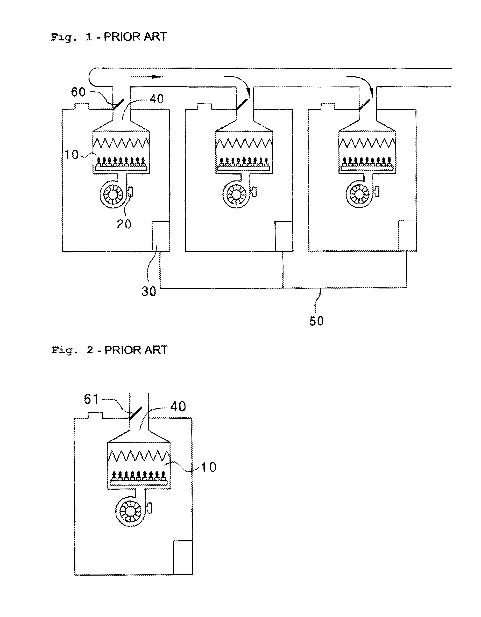
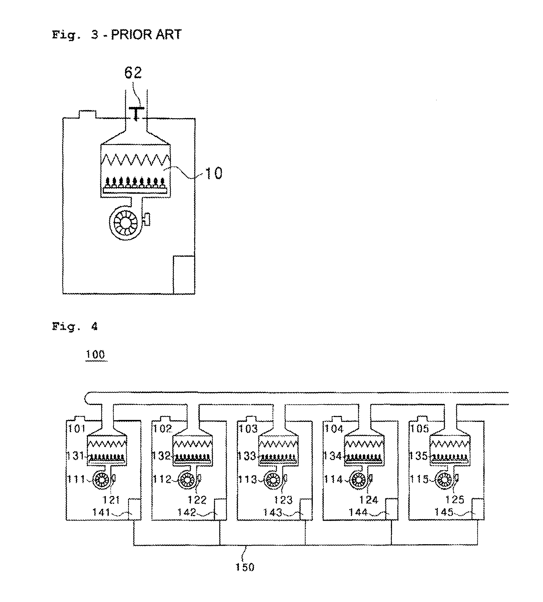
However, as the dampers 61, 62 are mechanically operated, their performance deteriorates when they are used over a long period of time, and as a result, there is a problem in that they will not perform their function as dampers.
Accordingly, critical damage may be caused by backflow of exhaust gas when the dampers are not operating normally.

Method used


Image

  • Multi-boiler and control method thereof for preventing back flow of exhaust gas
  • Multi-boiler and control method thereof for preventing back flow of exhaust gas
  • Multi-boiler and control method thereof for preventing back flow of exhaust gas

Examples


Embodiment Construction

[0031]The configuration and operation of preferred embodiments of the present invention are described hereafter in detail with reference to the accompanying drawings. Giving reference numerals to components in the drawings herein, it is noted that the same components are designated by substantially the same reference numerals, even though they are shown in different drawings.

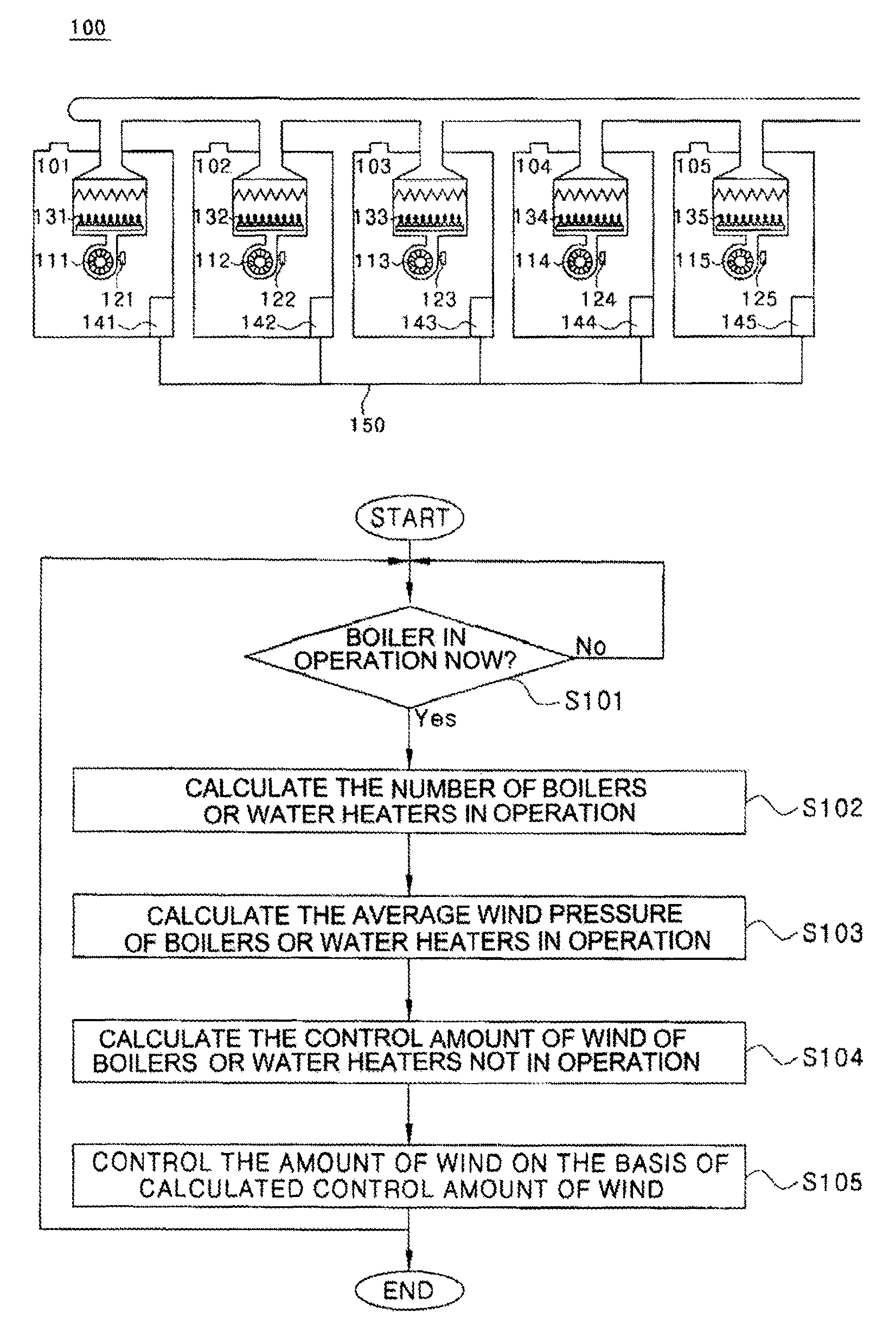
[0032]FIG. 4 is a schematic view showing a multiboiler 100 according to an embodiment of the present invention, which is comprised of, for example, five boilers or water heaters (hereinafter “boiler”) connected in a line.

[0033]Boilers 101, 102, 103, 104, 105 constituting the multiboiler 100 according to an embodiment of the present invention respectively include: fans 111, 112, 113, 114, 115 that send air into combustion chambers; wind pressure sensors 121, 122, 123, 124, 125 that measure the pressure of air flowing into the combustion chambers; burners 131, 132, 133, 134, 135; and controllers 141, 142, 143, 144...


PUM


Abstract

The present invention relates to a control method of preventing backflow of exhaust gas into combustion chambers of boilers or water heaters that are not in operation for a multiboiler comprising a plurality of boilers or water heaters connected in line, each of which including a wind pressure sensor measuring wind pressure of air flowing into a combustion chamber and a controller controlling a fan supplying air into the combustion chamber on the basis of the wind pressure measured by the wind pressure sensor. The control method includes measuring wind pressures using the wind pressure sensors in the operating boilers and calculating an average wind pressure, using any controller as a master controller to determine a control amount of wind of the fans of non-operational boilers based on the average wind pressure, and operating the fans of the non-operational boilers on the basis of the control amount of wind.

Description

CROSS-REFERENCE TO RELATED APPLICATIONS[0001]The present application is a national stage application under 35 U.S.C. §371 of International Application No. PCT / KR2008 / 007707 with an international filing date of Dec. 26, 2008, and claims priority of KR 10-2008-0046705 filed May 20, 2008.BACKGROUND OF THE INVENTION[0002]1. Field of the Invention[0003]The present invention relates to a multiboiler or a multi-water heater (hereinafter “multiboiler”) for preventing exhaust gas backflow and a method of controlling the same, and more particularly, to a multiboiler that prevents exhaust gas backflow using a wind pressure sensor and a controller which are provided for each boiler without having a damper, and a method of controlling the multiboiler.[0004]2. Description of the Related Art[0005]In general, combustion apparatuses such as a boiler or a water heater are designed to correspond to each desired capacity. However, there is a method of arranging and using a plurality of low-capacity boi...

Claims


Application Information

Patent Timeline
Patent Type & Authority Patents(United States)
IPC IPC(8): F23N1/02F24H9/20F24B1/189F24D9/00
CPCF24H9/2042F23N3/002F23N3/082F23N5/242F24D12/02F24D19/10F24D2200/043F23N2031/28Y02B30/14F23N2037/02F23N2041/06Y02B10/70F23J2211/20F23N2033/08F23N2231/28F23N2241/06F23N2233/08F23N2237/02Y02B30/00F24H9/20F24H9/00F24H15/242F24H15/35F24H15/443
Inventor KIM, SI-HWAN
Owner KYUNGDONG NAVIEN
Learn More