
Powdered medication inhaler

a technology of inhaler and powder, which is applied in the field of powder dispenser assemblies, can solve the problems of less favored aerosol devices, a large part of the devices now on the market, and harmful to patients by excessive amount of powder administration

Inactive Publication Date: 2001-06-05
MERCK SHARP & DOHME CORP
View PDF29 Cites 160 Cited by
  • Summary
  • Abstract
  • Description
  • Claims
  • Application Information

AI Technical Summary

Problems solved by technology

This is because such medicaments are often quite potent, and the administration of excessive amounts thereof could be harmful to the patient.
Further, if the dosage that is delivered is too small, it will not serve its purpose.
With the current concern over environmental issues, however, aerosol devices, which constitute a large part of the devices now on the market, are less favored.
Further, with aerosol devices, the medicament is dissolved or suspended in a liquid propellant mixture, which results in the introduction of unneeded chemical substances into the body and further adds to the complexity of the devices.
It has been determined that one of the likely reasons for this is the swirl nozzle design which does not sufficiently break up the hard agglomerates.
Another potential problem with such design is that the screw threads on the cap and adapter provide a condition in which the cap may be prematurely pulled off due to the tolerances of the screw threads.
As a result, the dispenser may not be turned a full 180.degree., as required.
Thus, the proper dosage may not be provided, and the counter mechanism may not be activated.
Further, by prematurely pulling the cap off, it may not be possible to easily reapply the cap to the dispenser to close the same.
Also, positioning of the cap for the rotating operation may not always result in accurate alignment.
Another possible problem is that of securing the powder retainer to the metering dose plate.
If a hot melt adhesive is used, the adhesive may leak into the mesh, so that quality and consistency is not obtained.
Further, by heating the same, there may be a distortion in the flatness and / or damage to the mesh.
A yet further potential problem is that the pawl used in the counter mechanism of the primary embodiment thereof requires an additional metal spring to be inserted therein.
This increases the number of parts, makes assembly more difficult, provides a pawl assembly that is not totally moldable and does not always provide a totally reliable counter mechanism.
Although a totally molded spring and pawl assembly is disclosed in a later embodiment thereof, such totally molded spring and pawl assembly is more difficult to mold and is not as satisfactory in use to that of the primary embodiment.
A still further potential problem relates to the indicia on the continuous and intermittent counter rings of the counter mechanism, that is, the dispenser must be tipped to a horizontal position to read the numbers, rather than providing the indicia for reading while the dispenser remains in its normal upright position.
Lastly, the swirl nozzle and mouthpiece can be fairly easily disengaged from the drive body during inhalation, possibly resulting in swallowing of the same or choking.
The same considerations are not applicable to disengagement of the mouthpiece from the swirl nozzle because of the inclined sides of the mouthpiece.

Method used


Image

  • Powdered medication inhaler
  • Powdered medication inhaler
  • Powdered medication inhaler

Examples


Embodiment Construction

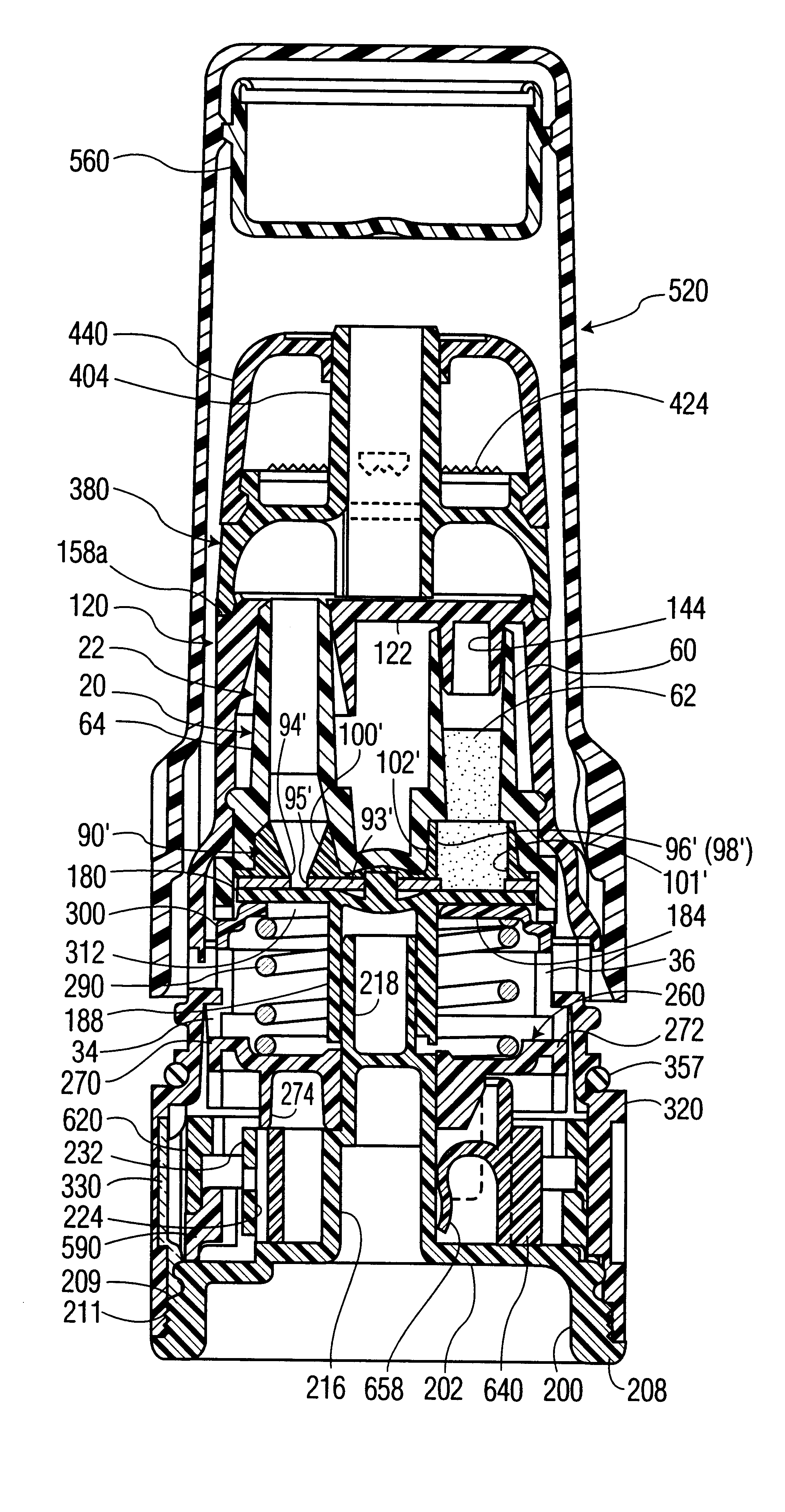
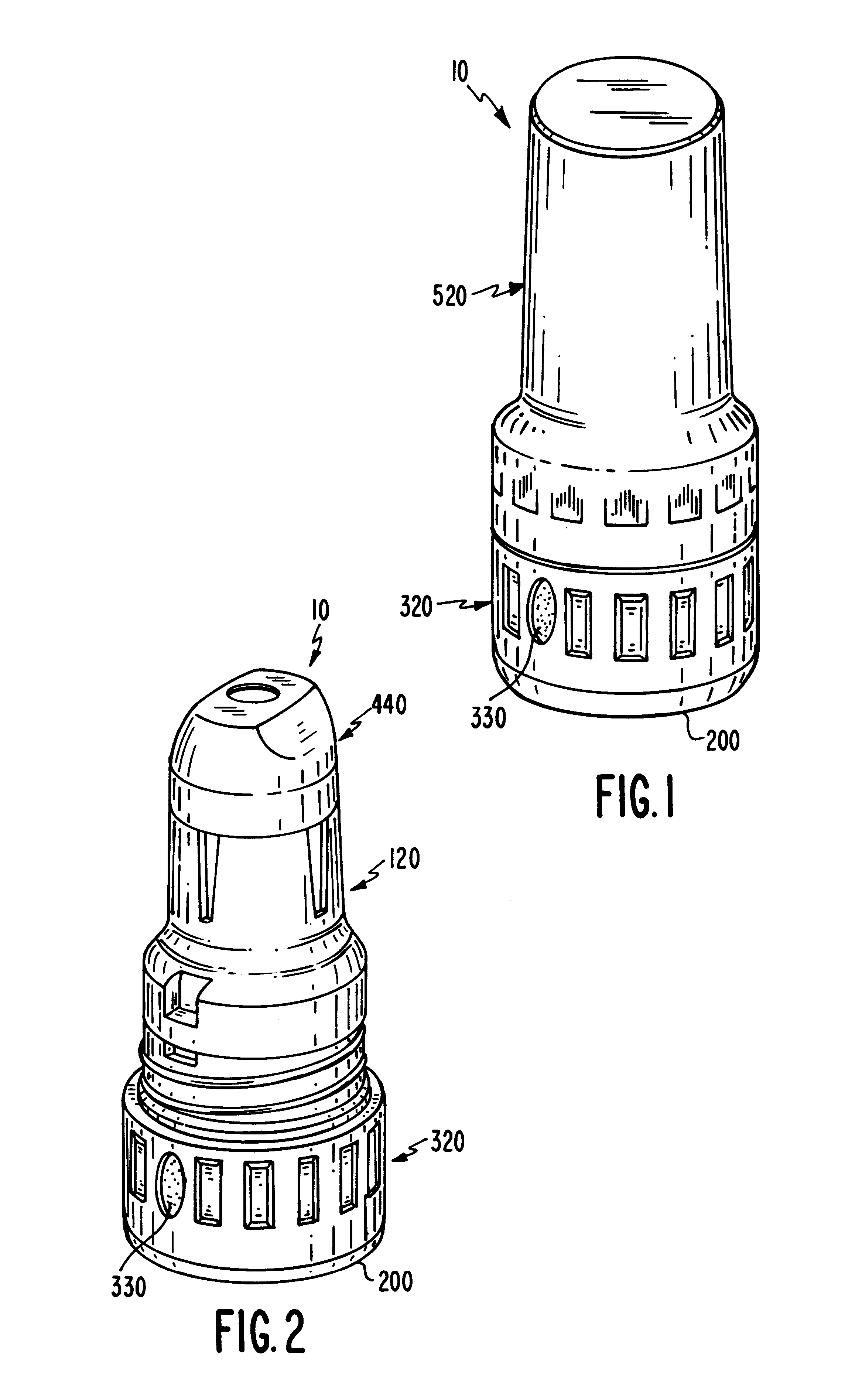
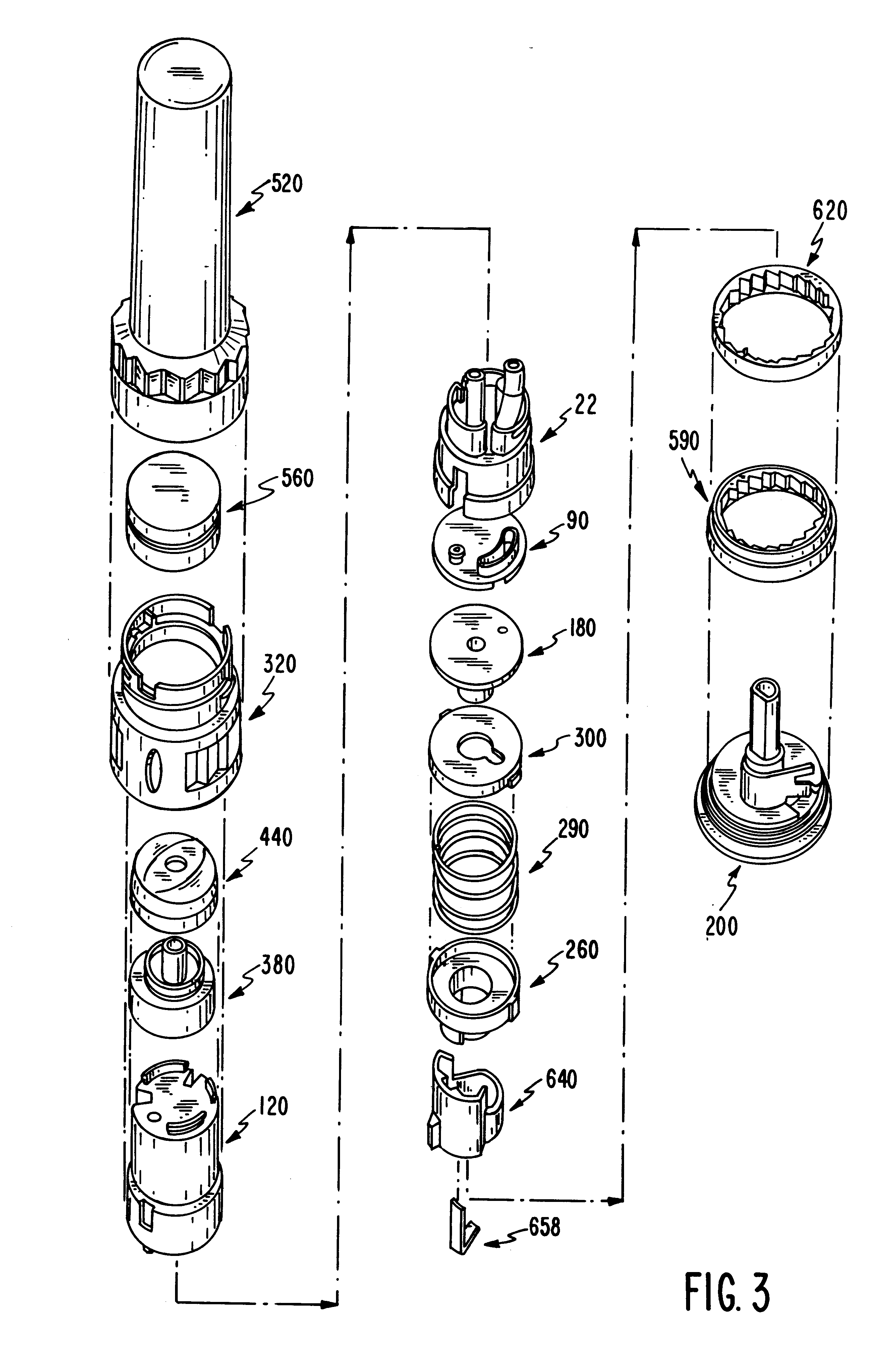
Referring to the drawings in detail, and initially to FIGS. 1-4 thereof, a metered powder dose dispenser 10 according to the present invention includes a powder housing 20 for holding a supply of powdered material to be dispensed, and for supplying metered doses of the powder to a user.

Powder housing 20 is comprised of a reservoir body 22, a reservoir plug 90 and a driving body 120, each preferably being formed as a single molded plastic piece.

Referring to FIGS. 3-8, reservoir body 22 includes a circular top wall 24 having an annular skirt 26 extending downwardly from the periphery of circular top wall 24. Annular skirt 26 includes an upper annular skirt section 28 with its upper end extending downwardly from the periphery of circular top wall 24, and a lower annular skirt section 30 extending downwardly from the lower end of upper annular skirt section 28. Lower annular skirt section 30 has an inner and outer diameter greater than the inner and outer diameters, respectively, of upp...


PUM


Abstract

A powder dispenser includes a reservoir body including a supply of powder and an inhalation conduit; a driving body for rotating the reservoir body and including upper recesses and two spring fingers in lower driving recesses thereof; a rotatable metering plate for carrying a metered amount of powder from the supply to the inhalation conduit, and having an underside with ribs; a gas permeable retainer welded to the ribs; a spring biasing the metering plate toward the reservoir body; a nozzle having spiked ribs welded in the upper recesses of the driving body and including a chimney with vertical flutes; an adapter non-rotatably mounted with respect to the metering plate and including two locking recesses for receiving the spring fingers for locking engagement and two helical cam tracks with a square cross-section; a closure cap covering the driving body and including priming ribs biasing the spring fingers out of the locking recesses and engaging with the locking recesses to rotate the driving body, and two cams riding within the cam tracks; a base non-rotatably connected with the metering plate; and a counter rotatably mounted on the base and including rotatable counter rings providing a visual count of the number of doses of powder to be dispensed, and a pawl assembly engaging with gear teeth of the counter rings for rotating the same, the pawl assembly including an outer wall, a pawl and a pawl spring integrally molded as a single piece.

Description

INTRODUCTION TO THE INVENTIONThe present invention relates generally to powder dispenser assemblies and, more particularly, is directed to a powder dispenser assembly used for inhalation of a metered dose of a powdered medicament.When delivering medicaments, that is, pharmacologically active compounds, in solid form to the respiratory tract and to the lungs, careful attention to the accuracy of the dosage, which can be smaller than 0.1 milligram, must be made. This is because such medicaments are often quite potent, and the administration of excessive amounts thereof could be harmful to the patient. Further, if the dosage that is delivered is too small, it will not serve its purpose.It is also necessary that the particles leaving the dispenser assembly be substantially within a particular size range, since particles of the medicament which are too large may not enter a desired lower portion of the respiratory tract, such as the bronchial tree or lungs, but instead will be deposited ...

Claims


Application Information

Patent Timeline
Patent Type & Authority Patents(United States)
IPC IPC(8): A61M15/00A61MA61M11/00
CPCA61M15/0065A61M15/0068A61M11/002A61M15/0025G06M1/163A61M2202/064A61M15/0073A61M15/008A61M15/0081A61M15/00
Inventor AMBROSIO, THOMAS J.BENSON, JR., WARREN A.DAO, KIM C.KENYON, DAVID J.KREISEDER, WALTER J.SCHONEBAUM, THEODORE J.VOGEL, ALLEN J.WALKER, LOUIS B.YANG, TSONG-TOH
Owner MERCK SHARP & DOHME CORP
Learn More