
Filter element and methods

a filter element and filter technology, applied in the field of filter elements, to achieve the effect of sufficient structural integrity

Inactive Publication Date: 2001-04-24
DONALDSON CO INC
View PDF26 Cites 155 Cited by
  • Summary
  • Abstract
  • Description
  • Claims
  • Application Information

AI Technical Summary

Benefits of technology

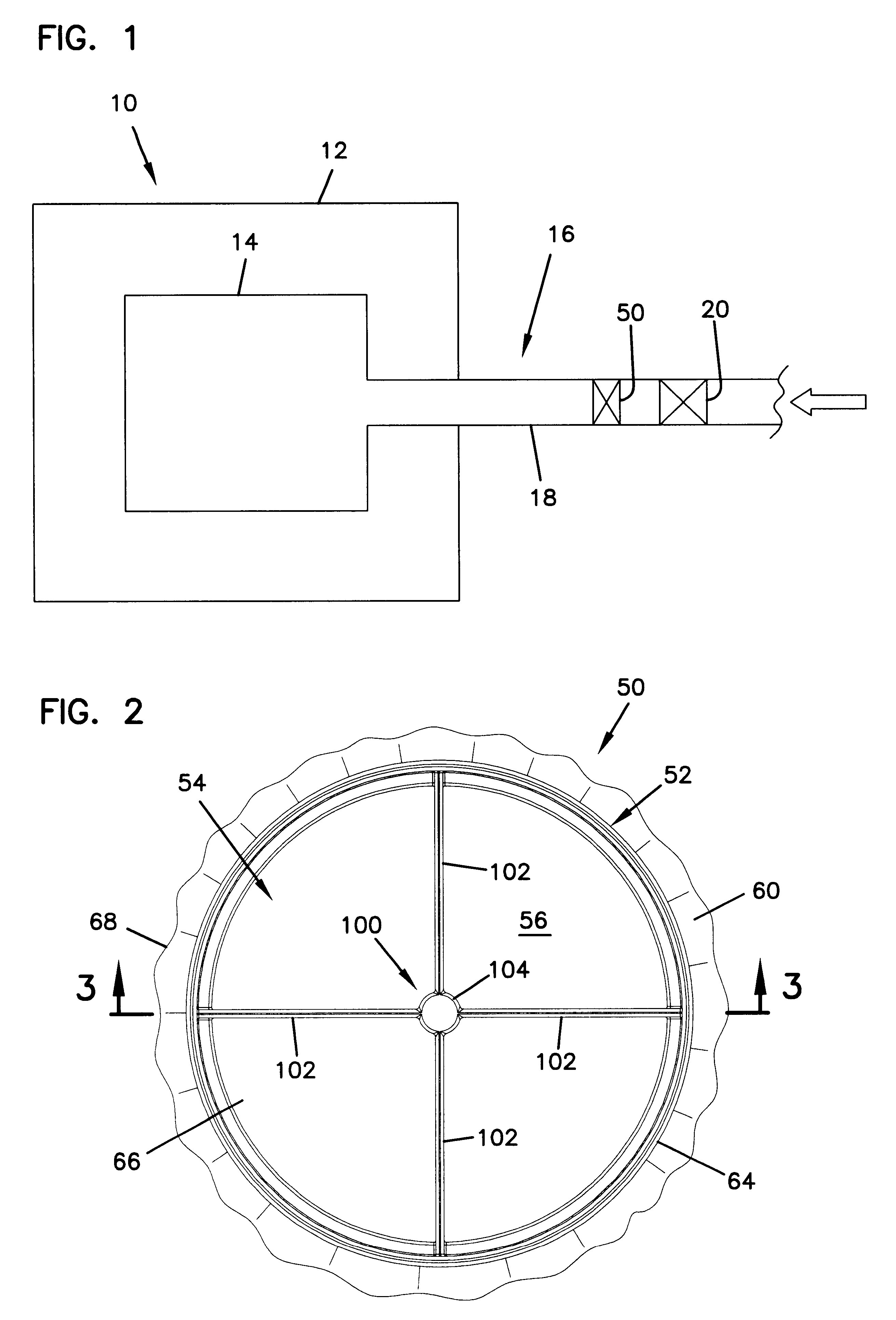
The air cleaner arrangements and constructions disclosed herein are usable in a variety of systems. FIG. 1 depicts one particular system, shown schematically at 10. In FIG. 1, equipment 12, such as a vehicle, having an engine 14 with some defined rated airflow demand is shown schematically. Equipment 12 may comprise a bus, an over the highway truck, and off-road vehicle, a tractor, or marine application such as a powerboat. Engine 14 powers equipment 12, through the use of an air, fuel mixture. In FIG. 1, airflow is shown drawn into the engine 14 through an air intake system 16. The air intake system may include a duct 18, and air is taken into the duct 18 at arrow 22. A primary element 20 is shown upstream of the engine 14 to remove particles and contaminants from the air. Downstream of the primary filter element is a secondary element 50. The secondary element is also upstream of the engine 14 to remove any larger particles and contaminants that did not get removed by the primary element 20. Further, the secondary element 50 helps to protect the engine 14 from any particles or contaminants that may be knocked loose of the primary element 20, when the primary element 20 is being serviced.
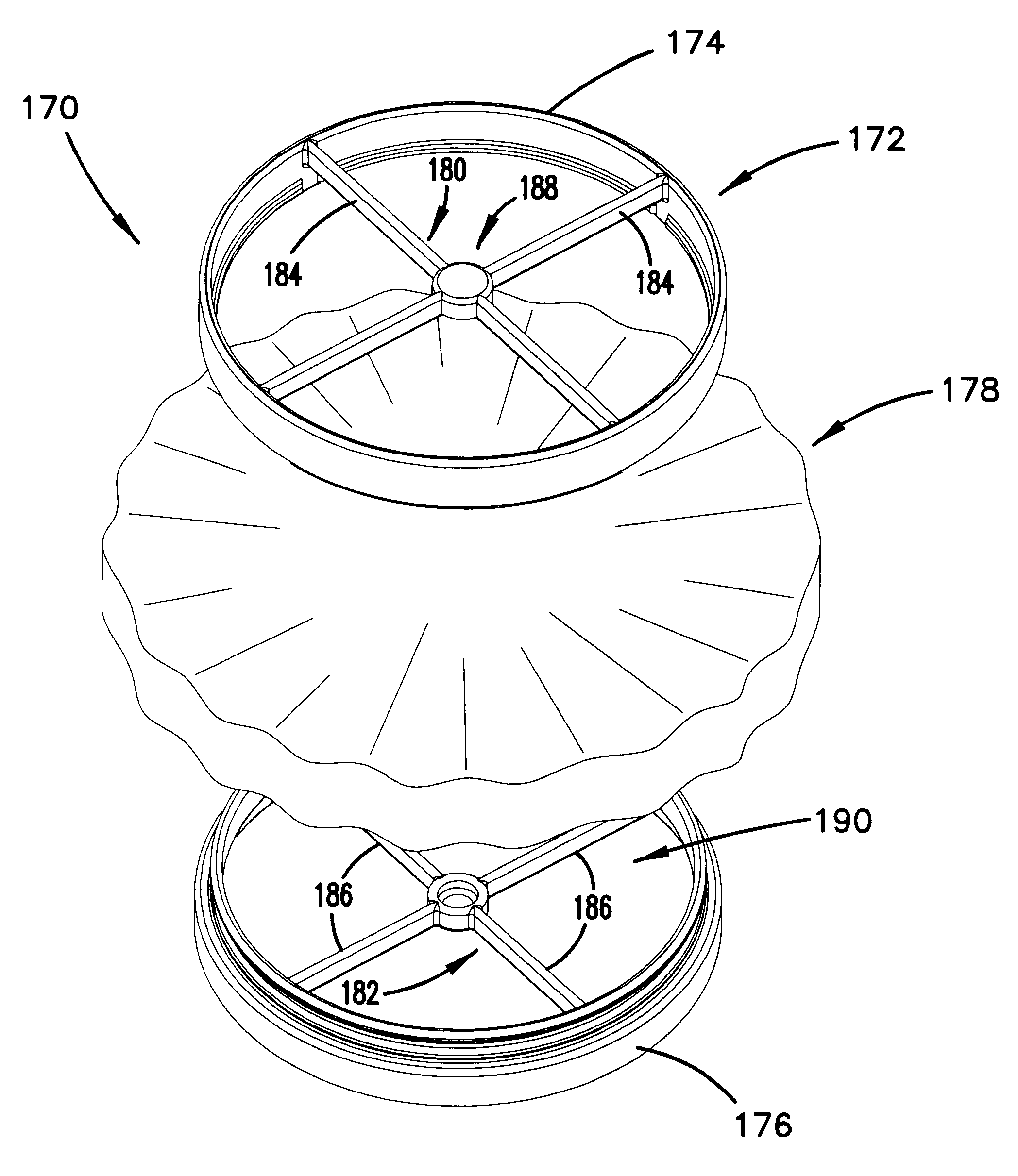
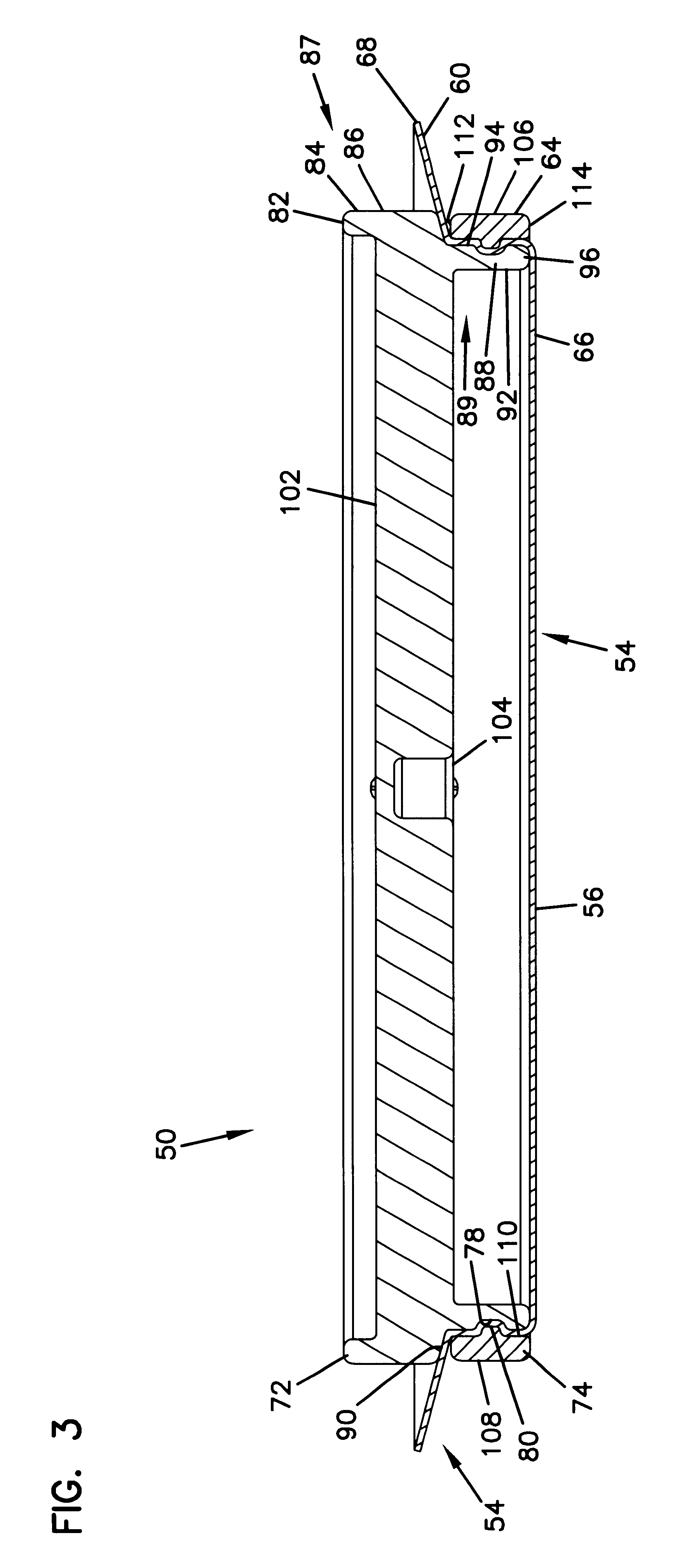
The new filter element can then be installed in the duct 18. This may be done by grasping the frame construction, such as the ribs 102 of the handle construction 100 and inserting it into the duct 18. The skirted portion 60 of the filter element becomes compressed between and against the frame construction and the inner wall of the duct to occupy or fill the volume therebetween and create a media-filled region and a sealing effect.

Problems solved by technology

Further, in many types of systems, the primary filter element becomes loaded with particulates, and needs to be replaced.

Method used


Image

  • Filter element and methods
  • Filter element and methods
  • Filter element and methods

Examples


Embodiment Construction

In this section, examples are provided of usable materials. The particular choice for any given material will vary, depending on the filtering application. In other words, the particular material selected for the systems usable herein will be decided upon by the engineer based on the system requirements. A variety of materials are possible. The following section provides examples of materials that have been found to be suitable.

The frame construction 52 will be constructed of a material that will provide structural integrity and is not subject to creep. Further, the frame construction 52 can be constructed of a non-metallic material such that it is environmentally friendly and either recyclable or readily incineratable. The frame construction can be constructed from most plastics, for example, glass reinforced plastic. One usable reinforced plastic is propylene or nylon.

The media 54 will be a media that will introduce little restriction into the duct. The media can be a nonpleated, ...


PUM

PropertyMeasurementUnit
Fractionaaaaaaaaaa
Fractionaaaaaaaaaa
Flow rateaaaaaaaaaa

Abstract

A filter element includes a frame construction and a region of media held by the frame construction. The region of media is oriented within the frame construction to remove at least some particulates from a gas stream passing therethrough. The region of media includes a skirted portion, wherein the skirted portion occupies a volume between the frame construction and a sealing surface of a duct, when the filter element is mounted within a duct. In preferred systems, the filter element may be used as a secondary element in the duct of an engine air intake or in a duct of an air cleaner housing. Methods of using and servicing filter elements are described herein.

Description

This disclosure relates to filters, filter constructions, and methods of filtering and servicing filters. In particular, this disclosure concerns filters for removing particulate materials from engine air intake streams.In general, air cleaner arrangements are utilized to filter combustion air intake streams for various engine applications, including for example, for vehicles and stationary engines. One typical approach has been to utilize a primary element to remove the bulk of particulates, and a secondary element, downstream of the primary element. The secondary element is used to catch larger particulate matter that may have, for one reason or another, made it past the primary filter element. For example, if the primary filter element fails, or becomes unsealed, the secondary element is oriented to protect the engine from any large particles and debris.Further, in many types of systems, the primary filter element becomes loaded with particulates, and needs to be replaced. During...

Claims


Application Information

Patent Timeline
IPC IPC(8): B01D46/10
CPCB01D46/0005B01D46/10B01D2279/60B01D2271/027
Inventor GIESEKE, STEVEN SCOTTBISHOP, WAYNE R. W.
Owner DONALDSON CO INC
Learn More