
Portable fluid transfer conduit

Inactive Publication Date: 2001-04-17
RPM IND LLC
View PDF27 Cites 39 Cited by
  • Summary
  • Abstract
  • Description
  • Claims
  • Application Information

AI Technical Summary

Benefits of technology

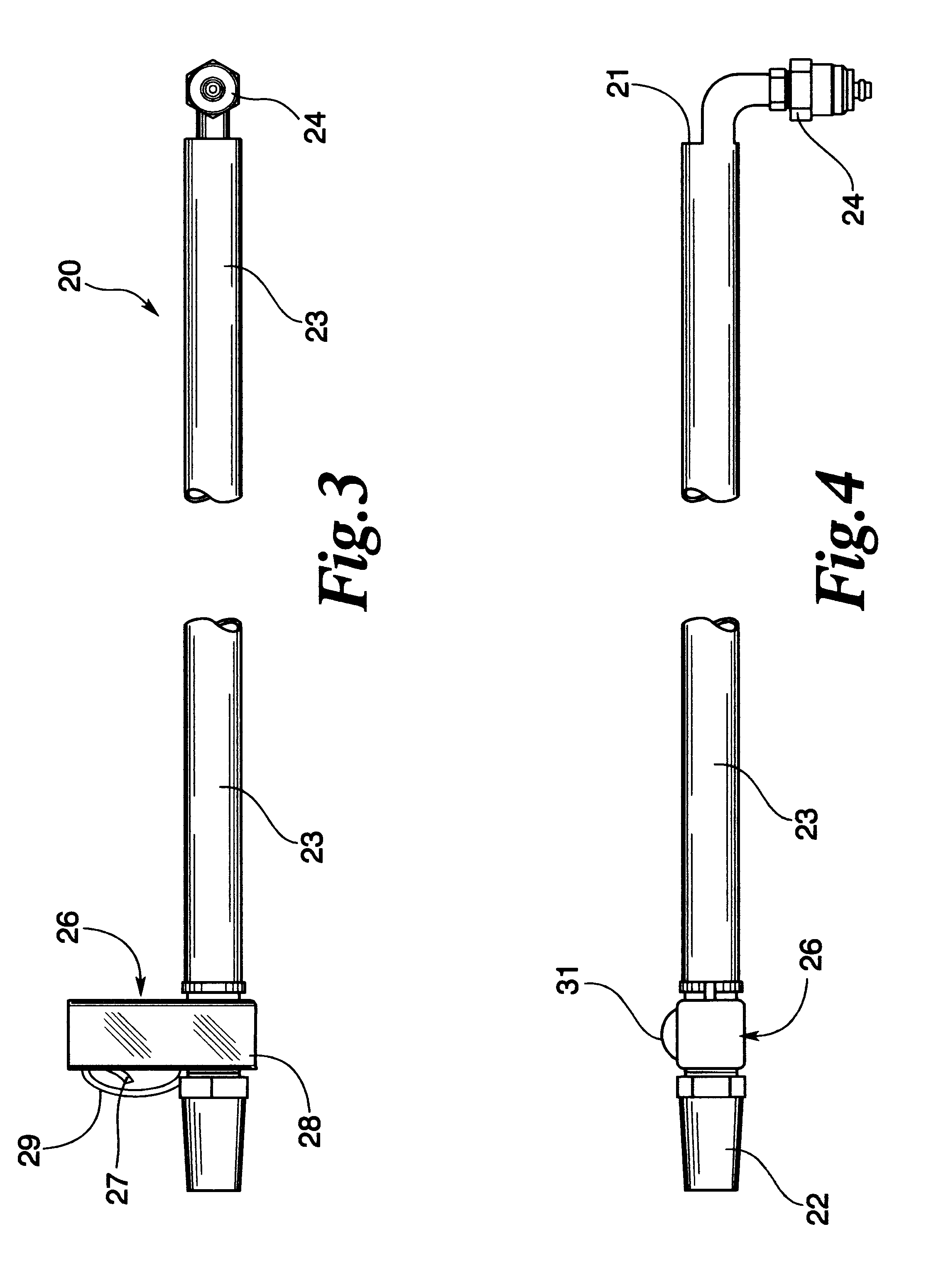
In another embodiment of the invention, a quick connect conduit having a female coupling is used to connect an air gun or supply source of air pressure. The conduit includes a fitting in the line between the prelubrication pump and the system filter. This is preferably used prior to the removal of oil from the system to clear oil channels and at least some of the oil from the filter to simplify oil removal and make it safer for the workers.

Problems solved by technology

Countless other examples exist, but what is generally common to these machines or equipment is the fact that the outlet port is inconveniently located.
Typically this is the result of having to remove the fluid from a sump or drainage point that is located at the bottom of the machine to utilize gravity flow.
While the task of removal is not difficult, it is often time consuming because of the inconvenient location of the fittings.
Additionally, there are numerous smaller devices and motors where access to fluid discharge ports is difficult to reach or in which the fluid must be assisted for removal.

Method used


Image

  • Portable fluid transfer conduit
  • Portable fluid transfer conduit
  • Portable fluid transfer conduit

Examples


Embodiment Construction

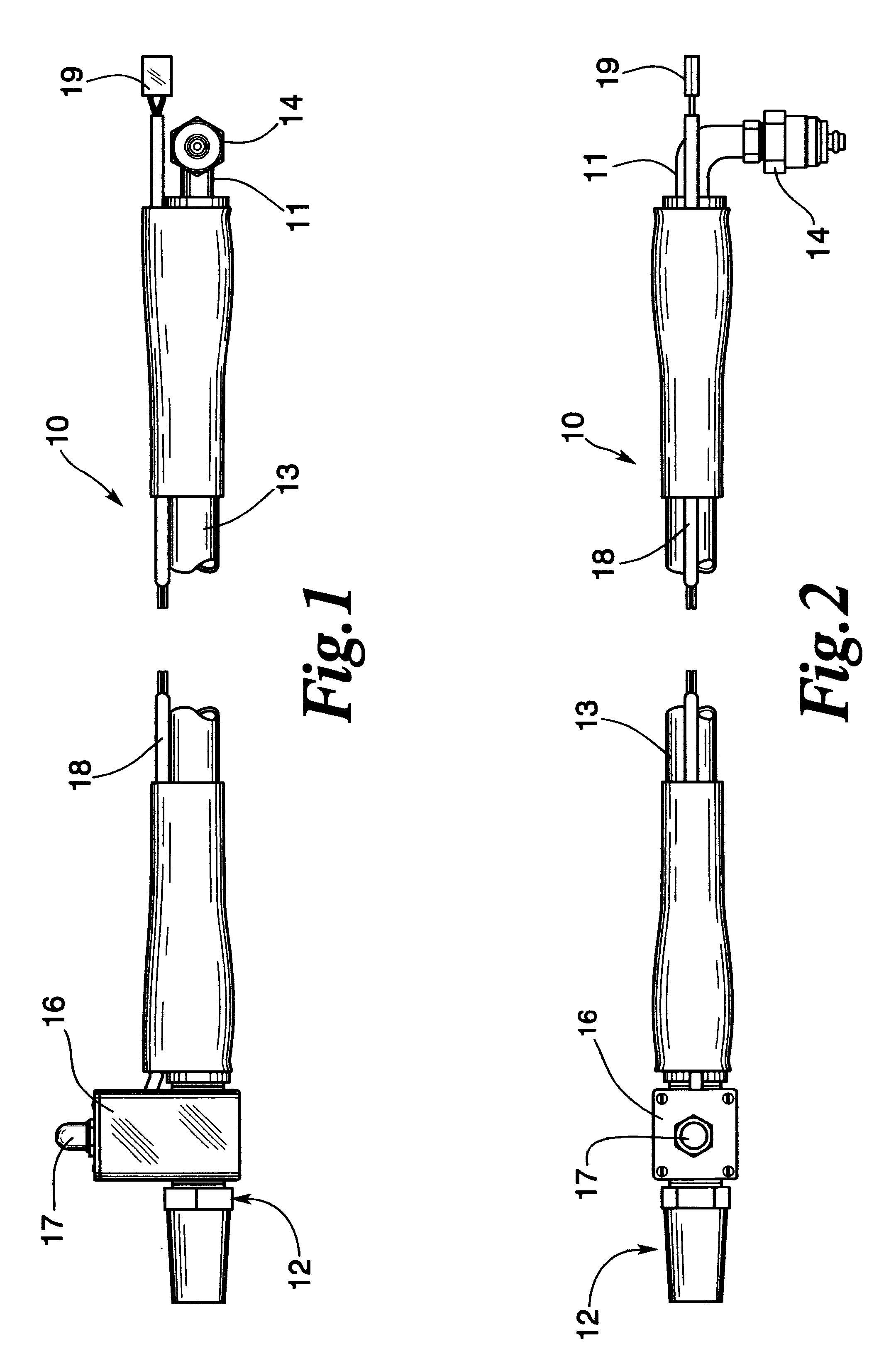
Referring to FIGS. 1 and 2, the present invention comprise a portable fluid transfer conduit 10 having an inlet port 11 and outlet port 12. Flexibly extending between inlet and outlet ports 11 and 12 is flexible tubing 13. Tubing 13 is preferably made from a natural or synthetic rubber material, braided stainless steel or polymeric extruded material such as polyethylene or styrene.

Attached to inlet 11 is coupling 14. As shown, coupling 14 is the male mateable end of a quick disconnect coupling more clearly shown in FIGS. 5 and 6. Alternatively, coupling 14 can be any type of fitting such as a screw in or a bayonet type coupling. Preferably, however, a quick connect fitting is adapted to the outlet of the fluid source. On devices such as a prelubrication pump similar to that shown in U.S. Pat. No. 4,502,431, a bypass or connector means is easily inserted on the pressure side of the pump to divert the oil from the engine to the fluid transfer conduit 10. An example is disclosed relati...


PUM


Abstract

A portable fluid transfer conduit is disclosed having an elongated flexible conduit having an inlet and outlet port. A coupling is postured at the inlet port for receiving fluid from a fluid source such as prelubrication pump. A flow control member is located at the discharge end which includes an activator for controlling the flow of fluid. The flow control member may include a portable pump where the fluid source does not have a powered flow.

Description

The present invention relates to fluid transfer conduit having flow control means and an adapter means for connection with a source of fluid, and, in particular, to a portable fluid transfer conduit that is useful in the removal of fluids from equipment which do not have conveniently located outlet ports.Many industrial machines and equipment have requirements for fluid exchanges. Examples of these include changing the oil in motors and engines or hydraulic fluid in presses and lifting equipment. Countless other examples exist, but what is generally common to these machines or equipment is the fact that the outlet port is inconveniently located. Typically this is the result of having to remove the fluid from a sump or drainage point that is located at the bottom of the machine to utilize gravity flow.While the task of removal is not difficult, it is often time consuming because of the inconvenient location of the fittings. However, in a number of the newer or retrofit machines, flui...

Claims


Application Information

Patent Timeline
IPC IPC(8): F01M11/04
CPCF01M11/0408Y10T137/6881Y10T137/8376Y10T137/86099
Inventor APOSTOLIDES, JOHN K.
Owner RPM IND LLC
Learn More