
Cleaning apparatus for an exhaust path of a process reaction chamber

a technology of process reaction chamber and cleaning apparatus, which is applied in the direction of cleaning process and apparatus, chemistry apparatus and processes, and electric discharge tubes, etc. it can solve the problems of affecting the smooth emission of exhaust gas, reducing productivity, and presenting safety risks. , to achieve the effect of improving worker safety, reducing the productivity of the associated process reaction chamber, and excellent cleaning

Active Publication Date: 2019-06-13
RETRO SEMI TECH LLC
View PDF3 Cites 0 Cited by
  • Summary
  • Abstract
  • Description
  • Claims
  • Application Information

AI Technical Summary

Benefits of technology

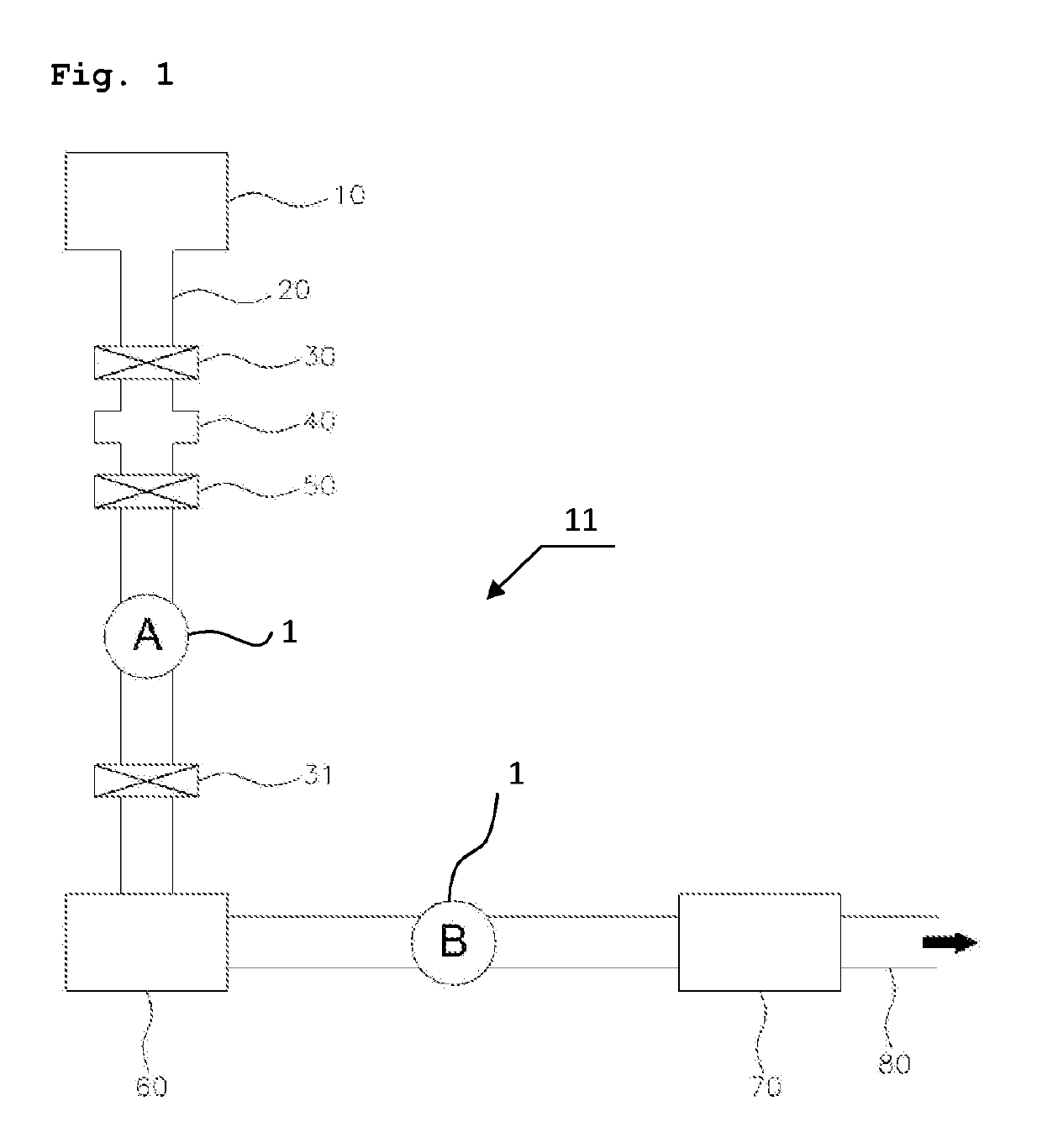
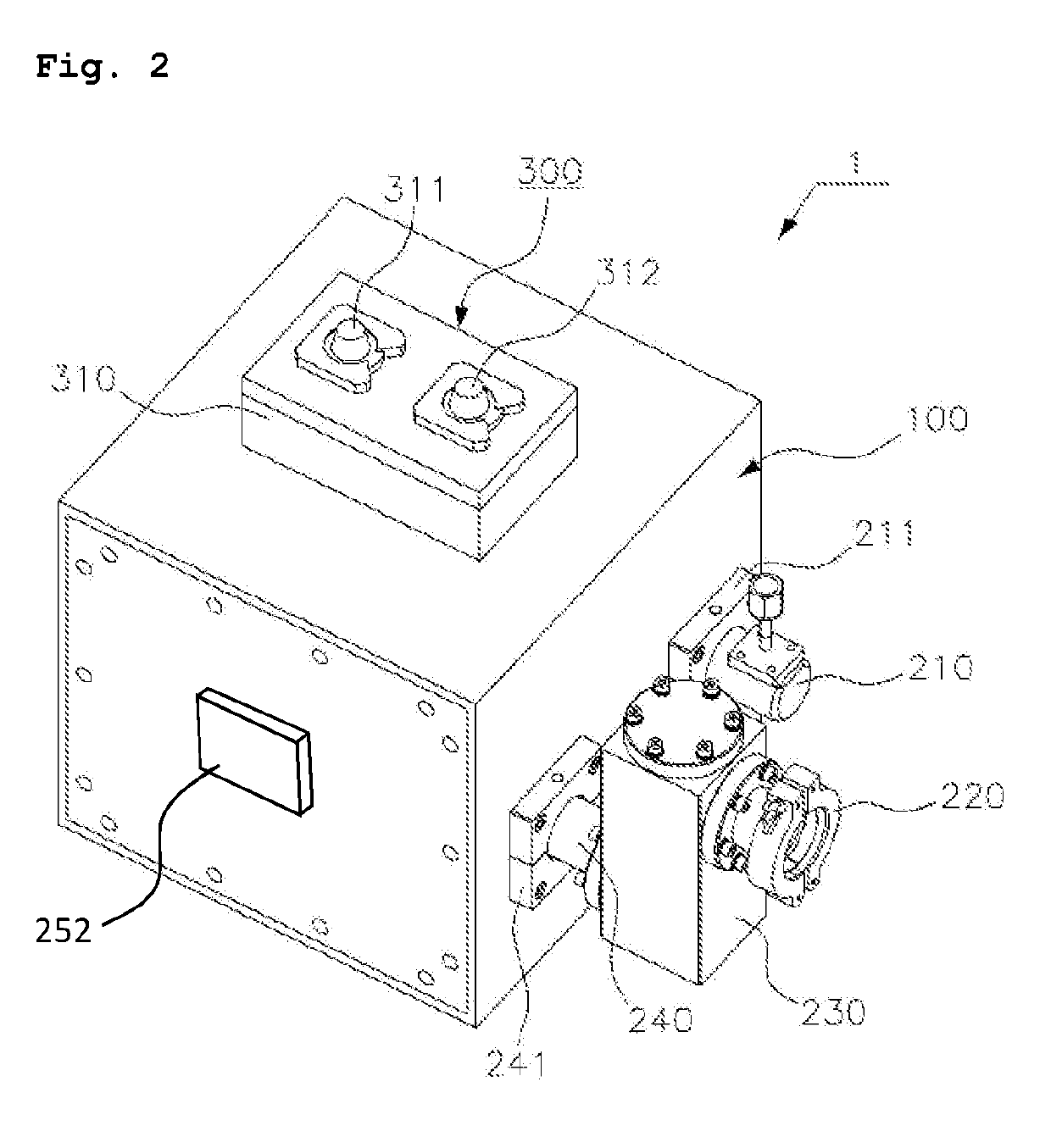
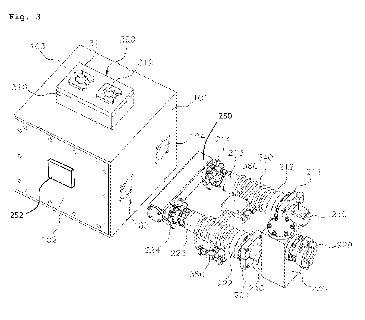
[0008]The present invention solves the conventional problems described above by providing a cleaning apparatus for the exhaust path of a process reaction chamber which can inhibit the accumulation of particulates in the exhaust path, thereby obviating reduced productivity of an associated process reaction chamber. Worker safety is improved because the exhaust path of the process reaction chamber is cleaned through the use of the presently disclosed cleaning apparatus and not through manpower. Excellent cleaning effect is achieved.
[0011]The cleaning apparatus of a process reaction chamber exhaust path of the present invention having a configuration as described has an effect that can obviate a reduction in productivity and can contribute to worker safety by cleaning the exhaust path of the process reaction chamber without the need for manual intervention.
[0012]Further, according to presently disclosed invention, fluorine radicals or chlorine radicals are formed twice in the cleaning apparatus, once in the inflow pipe and once in the outflow pipe, thereby exhibiting excellent cleaning effect.
[0013]Since the radio frequency power applied to the cleaning apparatus of the present invention is a radio frequency in the range of 40 to 100 MHz, the cleaning effect can be enhanced.

Problems solved by technology

However, solid precipitate generated by the deposition or etching process taking place within the process reaction chamber may enter the exhaust pipe and accumulate on an interior surface of the exhaust pipe.
Over time, this accumulation can cause operational failure of the gate valve or the pressure regulating valve or can lead to interference with the smooth emission of the exhaust gas by blocking the exhaust pipe.
However, since it is necessary to temporarily stop the reaction chamber processing during such manual cleaning, a decrease in productivity results.
In addition, since harsh chemicals are used in the manual precipitation removal process, safety risks are also always present.

Method used


Image

  • Cleaning apparatus for an exhaust path of a process reaction chamber
  • Cleaning apparatus for an exhaust path of a process reaction chamber
  • Cleaning apparatus for an exhaust path of a process reaction chamber

Examples


Embodiment Construction

[0026]In the following detailed description, numerous specific details are set forth in order to provide a thorough understanding of the various embodiments of the present invention. It will be understood by those of ordinary skill in the art that these embodiments of the present invention may be practiced without some of these specific details. In some instances, well-known methods, procedures, components and structures may not be described in detail so as not to obscure the embodiments of the present invention.

[0027]Exemplary embodiments of the present invention will be described below in more detail with reference to the accompanying drawings. The present invention may, however, be embodied in different forms and should not be construed as limited to the embodiments set forth herein. Rather, these embodiments are provided so that this disclosure will be thorough and complete, and will fully convey the scope of the present invention to those skilled in the art. Throughout the disc...


PUM


Abstract

A cleaning apparatus of an exhaust path of a process reaction chamber used in a manufacturing of articles including a semiconductor or an LCD. The cleaning apparatus of the exhaust path includes a housing having an inflow pipe, connected to an upstream end of the exhaust path, an outflow pipe, connected to a downstream end of the exhaust path, and a connecting pipe disposed between the inflow pipe and the outflow pipe. A radio frequency generator in the housing applies radio frequency power to the inflow pipe and to the outflow pipe via respective coils. Plasma induced within the inflow and outflow pipes from RF power applied via the respective coils causes the generation of radicals from the exhaust gas flowing within. The radicals act to dislodge accumulated particulates within the exhaust path downstream of the cleaning apparatus.

Description

STATEMENT REGARDING FEDERALLY SPONSORED RESEARCH OR DEVELOPMENT[0001]N / ABACKGROUND OF THE INVENTION[0002]The present invention relates to a cleaning apparatus for an exhaust path of a process reaction chamber used in a manufacturing process for semiconductors or LCDs, and more particularly, to a cleaning apparatus for the exhaust path in which an inflow pipe and an outflow pipe are formed inside a housing to which a gas inlet and a gas outlet are attached, radio frequency power from a radio frequency generator is applied to the inflow pipe and the outflow pipe, and a capacitor and a coil for impedance matching are provided.[0003]In general, a plasma generator is used in a process of depositing or patterning a structure implemented on a semiconductor or a liquid crystal display LCD. Plasma refers to an ionized gas state consisting of ions, electrons, or radicals, and is generated by a high-temperature state, a strong electric field, or a radio frequency (RF) electromagnetic field.[00...

Claims


Application Information

Patent Timeline
Patent Type & Authority Applications(United States)
IPC IPC(8): H01J37/32B08B9/027B08B7/00
CPCH01J37/32834H01J37/32183H01J37/3211H01J37/32862B08B9/027B08B7/0035H01J37/321H01J2237/335
Inventor KIM, DONG-SOOJOO, MIN-SUCHU, MIN KYU
Owner RETRO SEMI TECH LLC
Learn More