
Vacuum deposition of bus bars onto conductive transparent films

a technology of conductive transparent film and vacuum deposition method, which is applied in the direction of conductive layers on insulating supports, heater elements, synthetic resin layered products, etc., can solve the problems of brittle materials, disturbed conductive elements, poor results of both methods, etc., and achieve the effect of varying the thickness of bus bars

Inactive Publication Date: 2001-03-20
SOUTHWALL TECH INC
View PDF26 Cites 137 Cited by
  • Summary
  • Abstract
  • Description
  • Claims
  • Application Information

AI Technical Summary

Benefits of technology

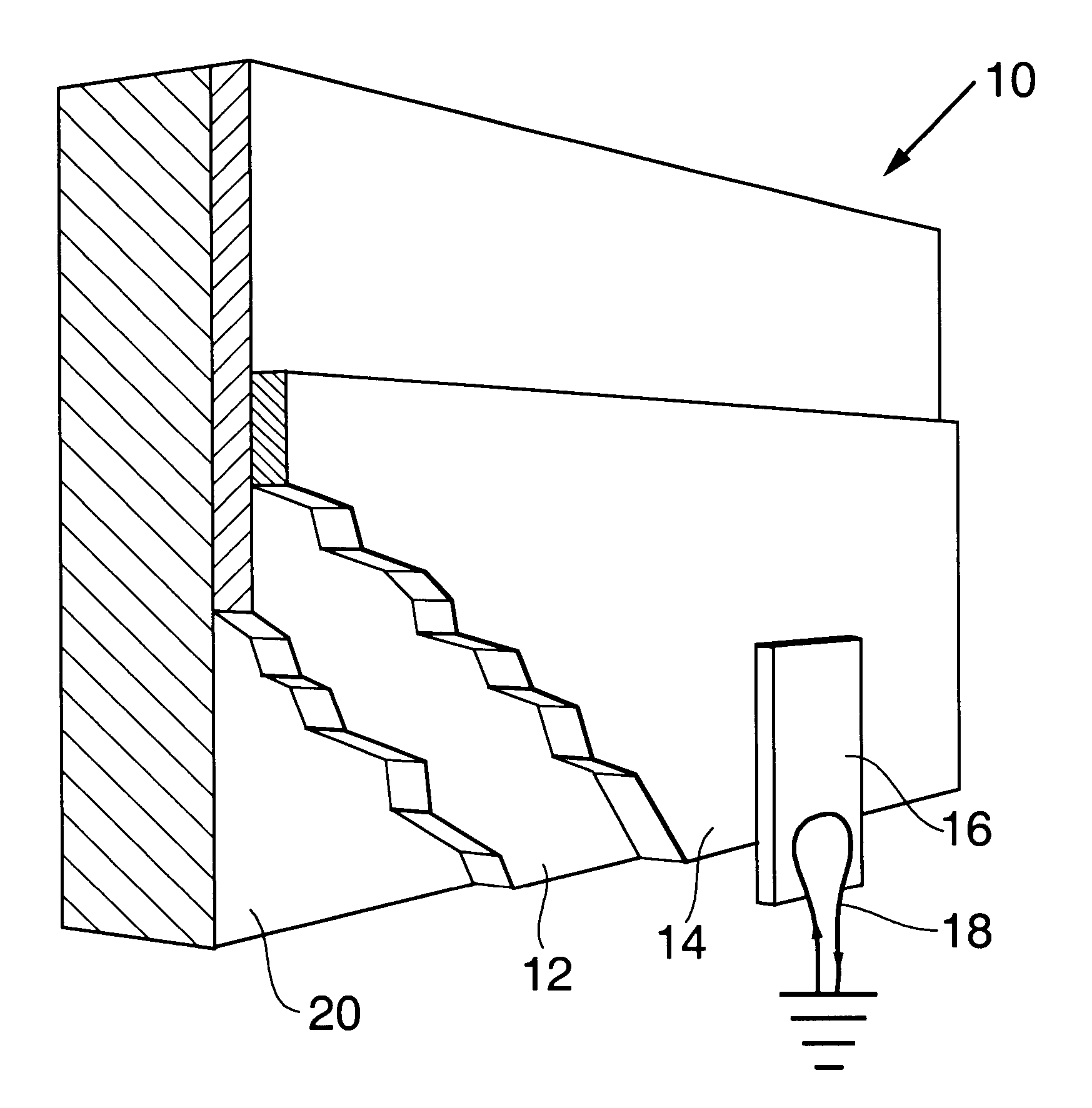
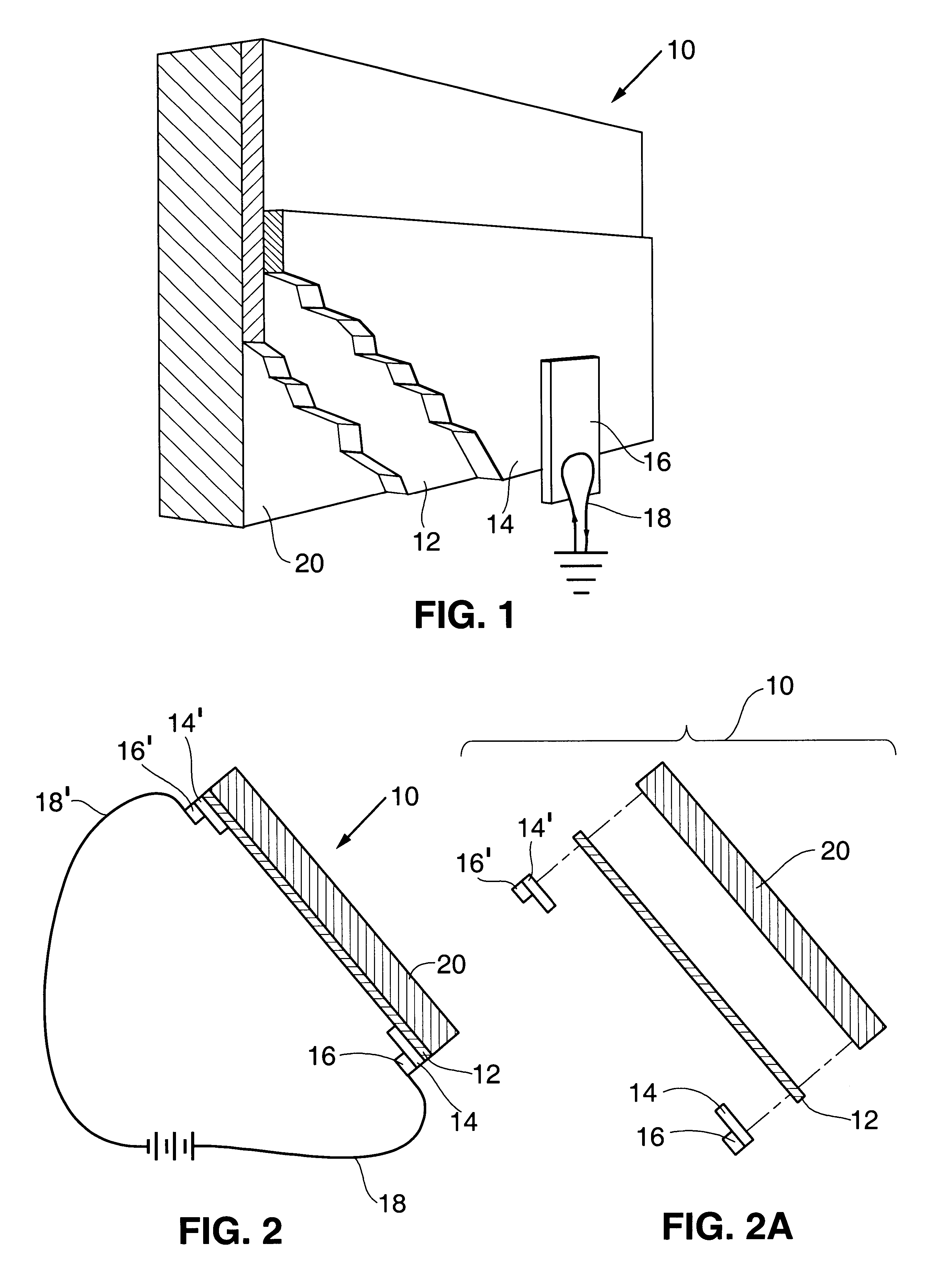
One advantage of the present invention is the versatility of vacuum deposition and its ability to produce bus bars which are shaped and graduated (tapered) in thickness. The various vacuum deposition methodologies generally involve laying down a layer of material (the bus bar) onto the conductive layer either as the conductive layer moves past the deposition zone or as the deposition zone moves over the conductive layer.
is the versatility of vacuum deposition and its ability to produce bus bars which are shaped and graduated (tapered) in thickness. The various vacuum deposition methodologies generally involve laying down a layer of material (the bus bar) onto the conductive layer either as the conductive layer moves past the deposition zone or as the deposition zone moves over the conductive layer.
As noted above, particularly in the case of multilayer conductive layers, sputter deposition is an excellent process for producing conductive layers. If this process is used it is often convenient to use it also to produce the bus bars and to do this in the same equipment in which the conductive layer is being laid down. In this case, the bus bars can be laid down immediately after the conductive layer is deposited. In fort, if desired, the bus bar could be laid down in between layers of a multi-layer conductive film.
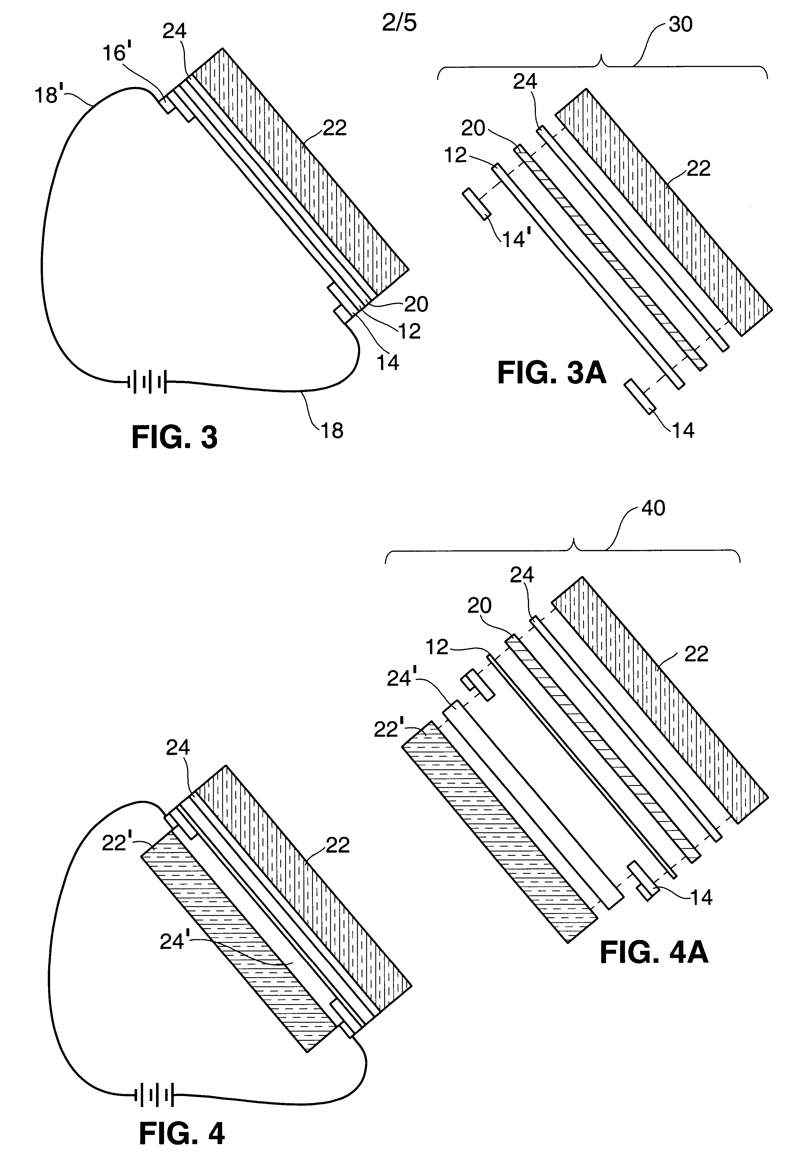
In the case of automotive glazings, such as windshields, a glass windshield blank can be coated with a conductive layer using the sputter depositer and thereafter bus bars can be sputtered onto opposing edges of the conductive layer on the glass blank. Alternatively, a plastic substrate can be coated with the conductive layer and thereafter the bus bars can be applied. In this case, the plastic substrate is typically a continuous web and the bus bars need to be patterned or shaped to correspond to opposing edges of the windshield. The substrate is cut into pieces corresponding to the windshield shape and laminated into the windshield structure. Representative methods for shaping the bus bars are described below.
It is also possible to vary the thickness of the bus bars. Varying bus bar thickness can be used to vary the conductivity of the connection to the conductive layer. This can give variations in the current passing through various portions of the conductive layer and, in the case of heated windshields and the like focus the heat in certain areas, such as near the windshield wipers where it will be most effective.
FIG. 7 shows a typical windshield-shaped conductive layer 12 with bus bars 14 and 14' on opposing edges. Bus bars 14 and 14' are shaped to follow the edges of layer 12. In addition, as shown by cross section 8-8.sup.1 shown in FIG. 8, the bus bars 14 and 14' can be tapered. As shown in the cross section 9-9.sup.1 depicted in FIG. 9, the thickness can be varied from thick areas such as 90 and 90' to thinner area such as 92.

Problems solved by technology

Both of these methods gave poor results.
The materials are brittle and require high temperature firing which can disturb delicate conductive elements.
Electrodeposition of conductive connectors has also been used but has the disadvantage of employing wet chemistry which is typically different than and not particularly compatible with the other processes employed in the production of the conductive thin films.

Method used


Image

  • Vacuum deposition of bus bars onto conductive transparent films
  • Vacuum deposition of bus bars onto conductive transparent films
  • Vacuum deposition of bus bars onto conductive transparent films

Examples


example 1

(sputtered bus bars):

A 13.5 inch wide polyester film carrying the conductive layer just described was coated with a pair of 3.5 inch wide silver bus bars in a laboratory roll coater. The bus bars were 4.5 inches apart and ran downweb along the substrate. The two bus bars were applied from a single silver target which was masked in the center to provide the transparent region between the two electrodes. The bus bars were about 100 nm thick.

A 1.5 by 6 inch safety glass laminate was prepared by inserting the coated plastic film with sputtered bus bars between two 15 mil plies of PVB (i.e. RB11 Saflex manufactured by Solutia). The conductive interlayer was then placed between two 2.1 mm thick pieces of float glass and bonded in a Carver (model 2518) heated press. The laminating conditions in the Carver Press were ramping up for 20 minutes from room temperature to 120.degree. C. followed by 30 minutes at the constant temperature of 120.degree.. The pressure was set to about 80 lbs / in.sup...


PUM

PropertyMeasurementUnit
wavelengthaaaaaaaaaa
Transparentaaaaaaaaaa

Abstract

Vacuum deposition processes such as sputter-depositing are employed to deposit electrically conductive bus bars onto thin film transparent conductor sheets. These assemblies provide efficient and durable electrical connections to the conductor sheets which can be laminated into glazing structures such as automotive windshields to provide resistance heating for defogging and deicing or the provide an electrical connection for in-window antennas and in window radiation shields.

Description

1. Field of the InventionThis invention relates to electrically conductive transparent panels and to bus bars which make electrical contact with them. These transparent panels can take the form of window glazings, particularly vehicle windshields and the like. The electrical bus bars can be used to allow a powering current to be delivered to the panel to heat the panel such as for deicing or defogging a vehicle windshield. They also can be used to permit an electromagnetic signal, such as a radio signal, detected by the panel to be electrically transmitted from the panel.2. Background InformationThere are numerous applications where it is desired to have a transparent panel containing an electrically conductive element which is connected to an electrical circuit. Three very common applications of this sort are 1. vehicle window glazings which have conductive elements for providing electric heat to the windows to melt ice or defog; 2. vehicle window glazings which have conductive ele...

Claims


Application Information

Patent Timeline
Patent Type & Authority Patents(United States)
IPC IPC(8): B32B17/06B32B17/10B32B27/36H01Q1/12H05B3/84H05B3/86H05K3/24B60J1/00B32B9/00B60J1/20C03C17/36C03C27/12H01B5/14H01B13/00
CPCB32B17/10B32B17/10036B32B17/10174B32B17/10761H01Q1/1271H05B3/84H05B3/86H05B2203/016H05B2203/017H05K3/244B32B2367/00B32B17/10005B32B7/12B32B2333/08B32B2333/12
Inventor WOODARD, FLOYD E.FURLER, RETO
Owner SOUTHWALL TECH INC
Learn More