
Electrolytic process for producing chlorine dioxide

a technology of electrolysis and chlorine dioxide, which is applied in the direction of electrolysis process, electrolysis components, cells, etc., can solve the problems of preventing its use in many applications, and achieve the effect of improving the conversion efficiency per pass

Inactive Publication Date: 2001-03-20
STERLING PULP CHEM +2
View PDF16 Cites 59 Cited by
  • Summary
  • Abstract
  • Description
  • Claims
  • Application Information

AI Technical Summary

Benefits of technology

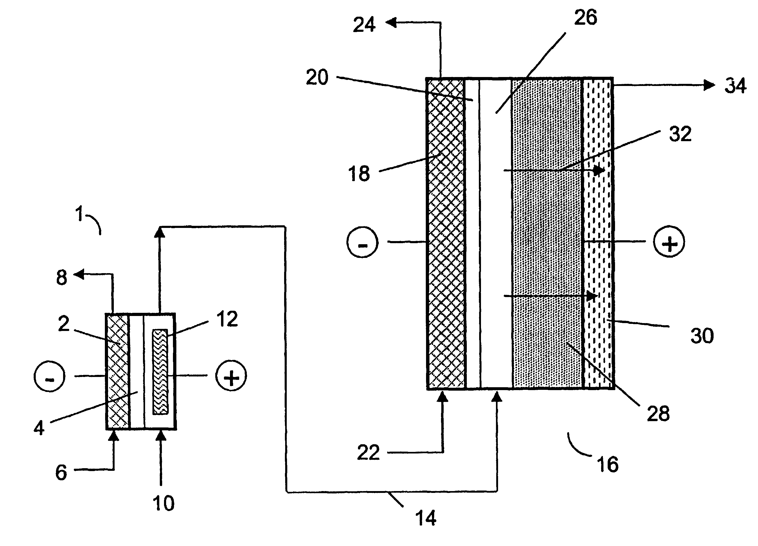
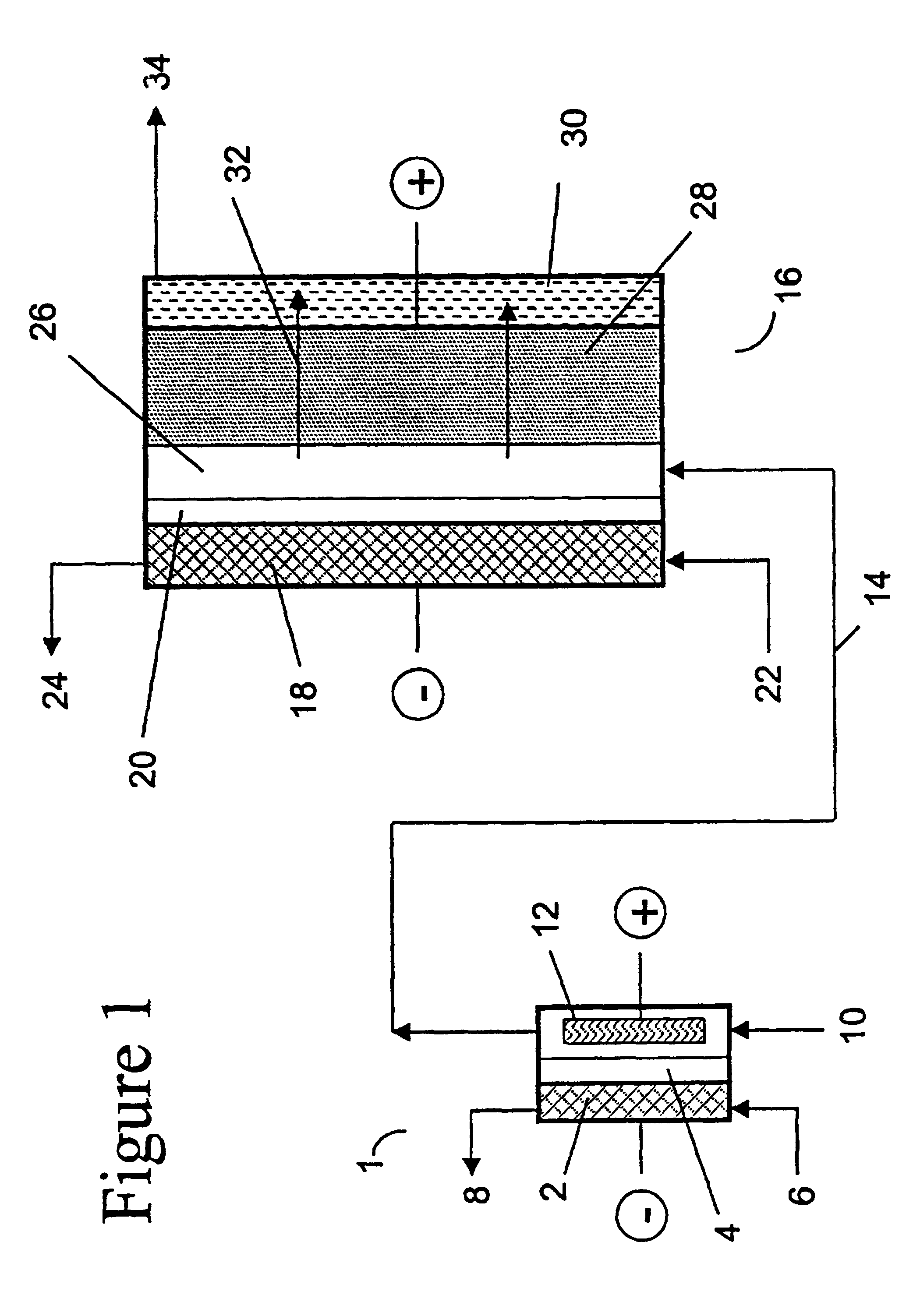
Surprisingly, it has been found that the combination of (1) using an electrochemical acidification cell to lower the pH value of the aqueous alkali metal chlorite feed to an optimum value before it enters the anode compartment of an electrochemical oxidation cell where the chlorite is converted to chlorine dioxide with (2) using an improved anolyte flow pattern in the electrochemical oxidation cell where the anolyte passes through a porous, high surface area electrode results in a substantially improved conversion efficiency per pass.
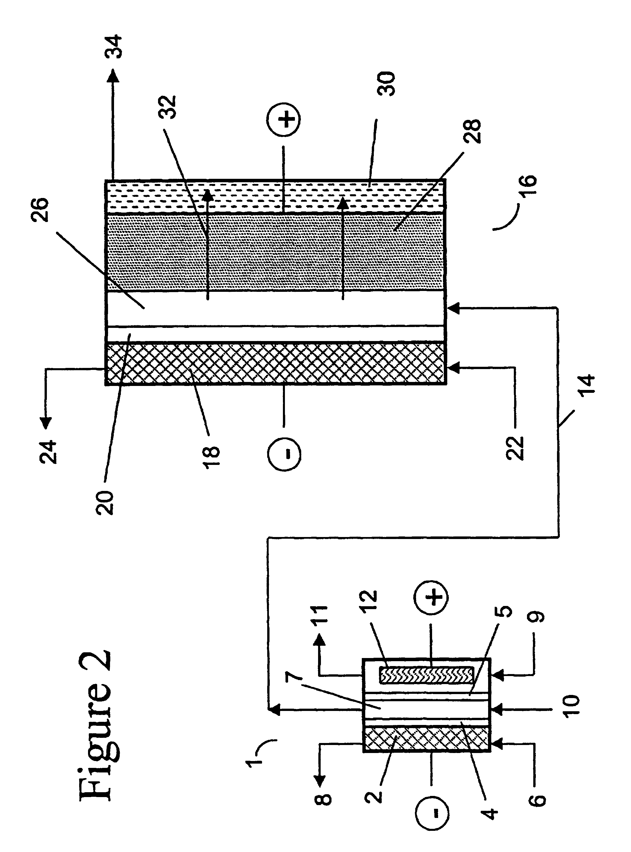
FIG. 2 shows an alternate three-compartment acidification cell 1 configuration where two cation membranes, 4 and 5, are used to form a central ion exchanging compartment 7 where alkali metal chlorite stream 10 can be fed upflow and exits as an acidified product effluent stream 14 to electrochemical oxidation cell 16. In this configuration, the alkali metal chlorite feed solution is not in contact with an anode, and can potentially minimize or prevent any side anodic oxidation reactions with the chemical components in feedstock stream 10. The electrochemical acidification cell 1 is preferably arranged in a zero gap configuration with anode 12 and cathode 2 in contact with membranes 5 and 4 respectively. Alternatively, either anode 12 or cathode 2 or both can be operated with a finite gap with the adjacent membranes.

Problems solved by technology

The product solution, in addition to chlorine dioxide, may also contain unconverted chlorite as well as undesired by-products, resulting from inefficiencies, such as chlorate or chloride ions.
However, the presence of unconverted chlorite and undesired by-products in the product stream may preclude its use in many applications.

Method used


Image

  • Electrolytic process for producing chlorine dioxide
  • Electrolytic process for producing chlorine dioxide
  • Electrolytic process for producing chlorine dioxide

Examples


Embodiment Construction

two-compartment electrochemical oxidation cell utilizing a zero gap anode and cathode design of the type denoted as 40 in FIG. 3 was employed to oxidize a sodium chlorite / sodium chloride mixture (the concentrations of NaClO.sub.2 and NaCl were 9.74 gpL and 10.0 gpL, respectively) in a single pass through the zero gap anode / cathode design electrolyzer. The projected membrane or electrode surface area was 232 cm.sup.2. The high surface area anode was manufactured from TySAR.RTM. WEP-12 material supplied by Olin Corporation. The anolyte flow rate was 30 ml / min.

The cathode compartment of the oxidizer was fed with 0.05 N NaOH at a flow rate of 20 ml / min. A current density of 0.25 kA / m.sup.2 was applied to the cell, resulting in a cell voltage of 3.4 V. In an experimental run involving pre-acidification of the chlorite feed to a pH of 2.65, the product stream contained 6.75 gpL ClO.sub.2, 0.66 gpL NaClO.sub.3 as well as 0.08 gpl unreacted NaClO.sub.2. Based on the product stream compositi...


PUM


Abstract

A process for converting in a single pass an aqueous alkaline pH, alkali metal chlorite solution into an aqueous chlorine dioxide-containing solution that involves the combination of (1) using an electrochemical acidification cell to lower the pH value of the aqueous alkali metal chlorite feed before it enters the anode compartment of an electrochemical oxidation cell where the chlorite is converted to chlorine dioxide with (2) using an anolyte flow pattern where the anolyte passes through a porous, high surface area electrode. This process results in a substantially improved conversion efficiency per pass.

Description

1. Field of the InventionThe present invention is concerned with the electrolytic production of chlorine dioxide from chlorite ions. More particularly, the present invention relates to the electrochemical process and the electrolytic cell structure used to manufacture a high purity aqueous chlorine dioxide solution from a dilute aqueous alkali metal chlorite solution.2. Description of the ArtIt is known to produce chlorine dioxide electrolytically by the electro-oxidation of chlorite ions.U.S. Pat. No. 2,163,793 describes an electrochemical chlorine dioxide generating process in which an aqueous solution of alkali metal chlorite and alkali metal chloride is electrolyzed in an electrolytic cell equipped with a porous diaphragm separating the anode and the cathode compartments.British Patent No. 714,828 describes a process for the production of chlorine dioxide by electrolyzing an aqueous solution containing chlorite and a water-soluble salt of an inorganic oxy-acid other than sulfuri...

Claims


Application Information

Patent Timeline
IPC IPC(8): C25B1/26C25B1/00
CPCC25B1/26
Inventor LIPSZTAJN, MAREKCOWLEY, GERALDKACZUR, JERRY J.
Owner STERLING PULP CHEM
Learn More