
Method of analyzing spot welded structures

a spot welding and structure technology, applied in the direction of manufacturing tools, material strength using steady bending force, instruments, etc., can solve the problems of mislead designers to inaccurately design spot welding structures out of an abundance of precautions, lack of increased accuracy and reliability, and failure to meet the requirements of so as to achieve structural safety and weight reduction without jeopardizing the risk of failure over the useful life of the structur

Inactive Publication Date: 2001-02-13
FORD GLOBAL TECH LLC
View PDF4 Cites 27 Cited by
  • Summary
  • Abstract
  • Description
  • Claims
  • Application Information

AI Technical Summary

Benefits of technology

It is another object of this invention to practice such method technique by use of novel test metal coupons for unitary of mixed failure modes; such coupons, when tested to failure, should provide increased accuracy for strength and stiffness data needed by the method technique herein.

Problems solved by technology

The unreliability of current methods to predict the failure mode of a specific spot welded joint in automotive bodies has misled designers to inaccurately design spot weld structures out of an abundance of precaution.
Existing structural analysis techniques for spot welded structures consider only two types of loadings or failure modes at any one time that may act on a structure; such method lacks the increased accuracy and reliability that will assist in structural safety and weight reduction without jeopardizing risk of failure over the useful life of the structure.

Method used


Image

  • Method of analyzing spot welded structures
  • Method of analyzing spot welded structures
  • Method of analyzing spot welded structures

Examples


Embodiment Construction

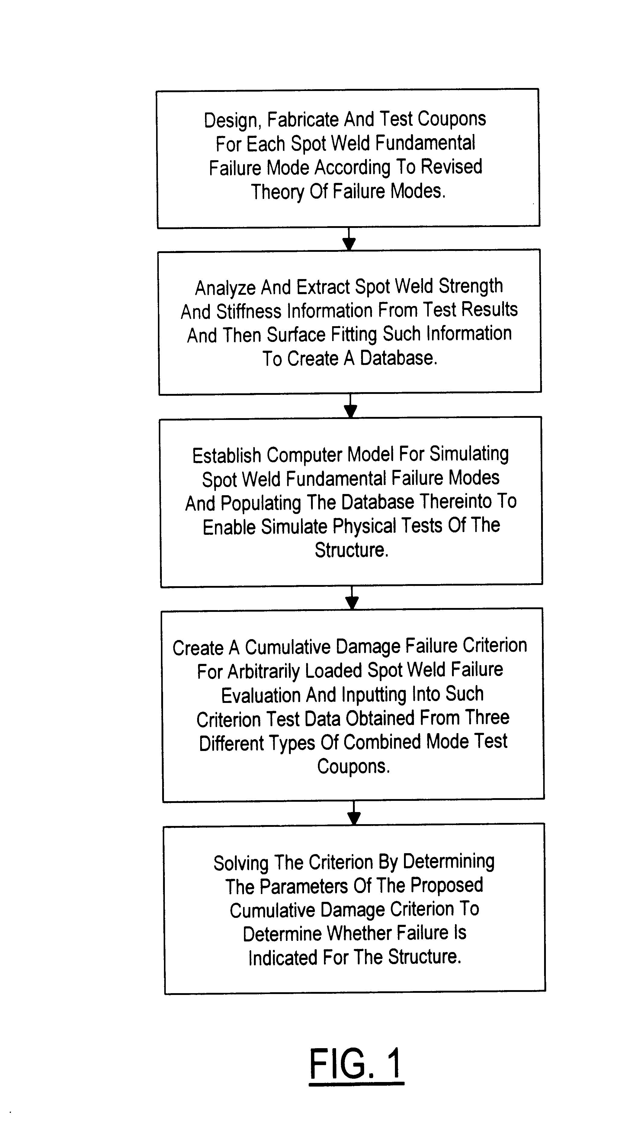
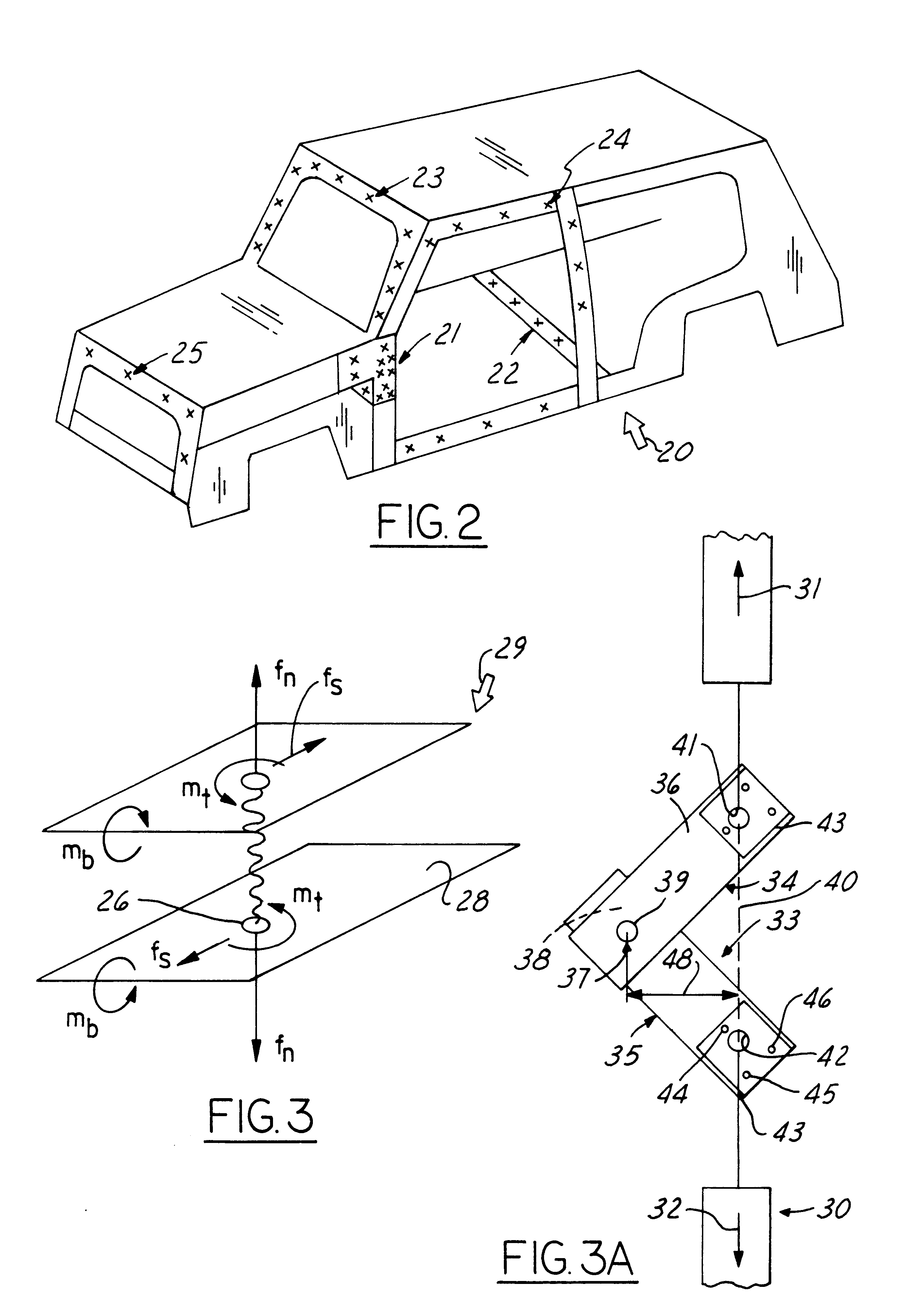
Referring to FIG. 1 (and step 1 thereof), four spot weld basic or fundamental failure modes are identified, which include shear tension, coach peel, normal pull tension and in-plane rotation; test coupons are designed, fabricated and tested for each of these basic modes. In step 2, the measured test results are analyzed so that spot weld strength and stiffness information can be extracted and fitted with math equations for each fundamental failure mode. The math fitting equations create test databases for use with computer math model simulations which are established in step 3. Once good correlations are reached between measured physical tests and computer math model simulations for single spot weld failure modes, step 5 requires a cumulative damage law or criterion to be used for evaluating spot weld failure under any arbitrary combined loading conditions. In step 6, the criterion is solved by use of law parameters that are determined and verified with at least three different comb...


PUM

PropertyMeasurementUnit
Thicknessaaaaaaaaaa
Forceaaaaaaaaaa
Strengthaaaaaaaaaa

Abstract

Method of analyzing spot welded sheet metal structures subjected to forces that promote one or more basic failure modes of either shear tension, in-plane rotation, coach peel, normal tension, or any combination of such basic modes, the method comprising: (i) providing spot welded sheet metal test coupons for analysis of the selected failure mode for the structure to be analyzed and subjecting such test coupons to progressively increasing forces that eventually achieve failure in the selected failure mode to thereby generate measured load and displacement test data; (ii) analyzing the data from the basic modes to derive and extract spot weld strength and stiffness information and then surface fitting such extracted data to create a database; (iii) establishing a computer math model for simulating the spot weld failure modes of the structure and populating the database thereinto to enable simulated physical tests of the structure; (iv) creating a cumulative-damage failure criterion for the spot welded structure that ratios (a) the resultant strength information from the populated math model for selected combinations of load and selected combinations of time and structure thickness, and (b) the measured strength information derived for such combinations of load derived from the test data; and (v) solving the criterion to determine whether it indicates failure for the combination of resultant strength and other values selected.

Description

1. Technical FieldThis invention relates to procedures for developing a resultant force based spot weld failure criterion for predicting multi-axial loaded spot weld failure.2. Discussion of Prior ArtSpot welding is widely used in joining sheet metal members in the manufacture of automotive bodies because such welding can be extremely fast. Spot welding is the simplest form of resistance welding in which electrodes apply some pressure when squeezingly contacting the sheet metal assembly while low voltage current, accompanied by sufficient amperage, is passed between the electrodes to locally raise the sheet metal to a melting and welding temperature.The strength and stiffness of the spot weld joints can vary considerably depending on the direction, complexity and cyclic nature of the joint loading. The unreliability of current methods to predict the failure mode of a specific spot welded joint in automotive bodies has misled designers to inaccurately design spot weld structures out ...

Claims


Application Information

Patent Timeline
IPC IPC(8): B23K11/11B23K31/12G01N3/00
CPCB23K11/11B23K31/12G01N3/00G01N2203/0296
Inventor WUNG, PEY MINSTEWART, WILLIAM STEVEN
Owner FORD GLOBAL TECH LLC
Learn More