
Chip performance optimization with self programmed built in self test

a self-testing, chip-based technology, applied in the direction of digital storage, instruments, measurement devices, etc., can solve the problem of its performance restricted by the slowest circui

Inactive Publication Date: 2001-02-06
IBM CORP
View PDF14 Cites 67 Cited by
  • Summary
  • Abstract
  • Description
  • Claims
  • Application Information

AI Technical Summary

Problems solved by technology

Consequently, even though such a chip may include individual circuits capable of higher performance, its performance restricted by its slowest circuits.

Method used


Image

  • Chip performance optimization with self programmed built in self test
  • Chip performance optimization with self programmed built in self test
  • Chip performance optimization with self programmed built in self test

Examples


Embodiment Construction

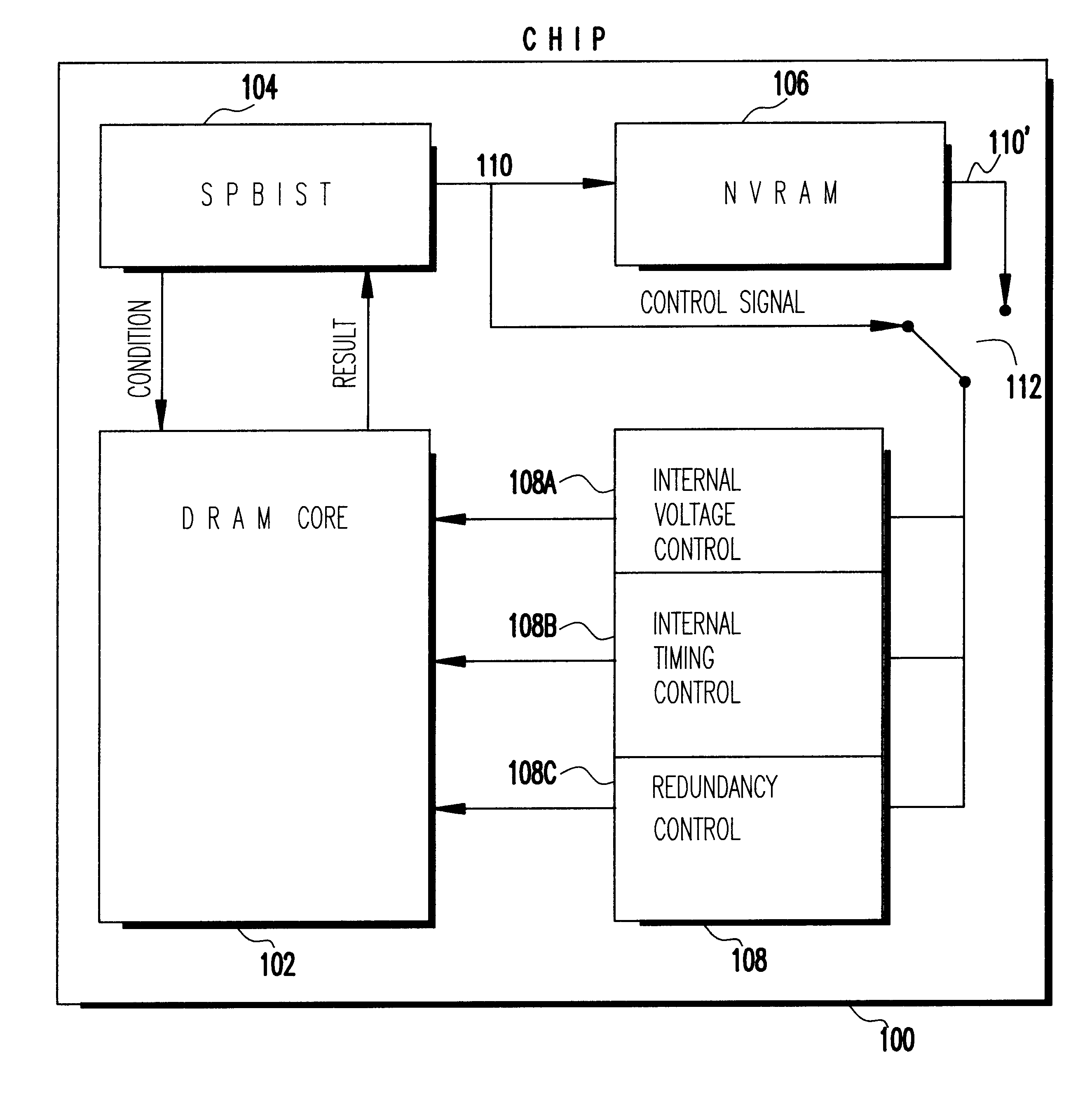
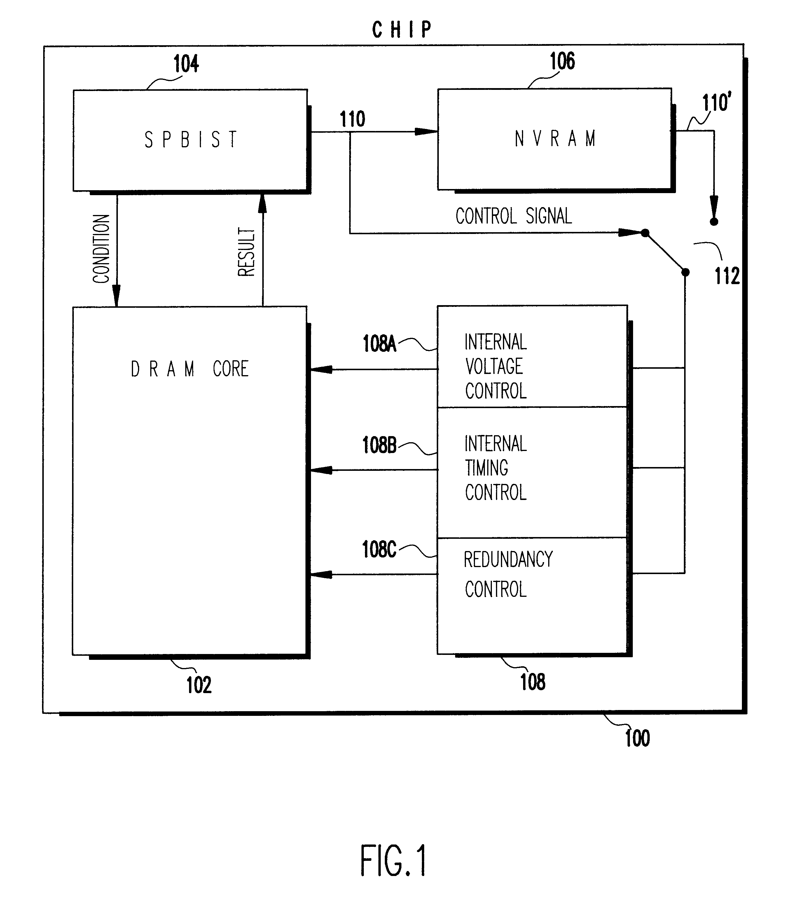
U.S. patent application Ser. No. 08 / 887,372 entitled, "DRAM with Self Programmed Built in Self Test" and U.S. patent application Ser. No. 08 / 887,462 entitled, "Method of Self Programmed Built in Self Test" both to Heidel et al., filed Jul. 2, 1997, assigned to the assignee of the present application and incorporated herein by reference, disclose a Dynamic Random Access Memory (DRAM) with Self Programmed Built in Self Test (SPBIST). U.S. patent application Ser. No. 08 / 887,374 entitled, "Built in Self Test With Memory" to Kirihata et al., filed Jul. 2, 1997, assigned to the assignee of the present application and incorporated herein by reference, discloses an integrated circuit chip that includes a DRAM with SPBIST that includes Non-Volatile Random Access Memory (NVRAM) for storing self test data and results.

For preferred embodiment integrated circuit (IC) chips, one test included in the self test finds the IC's optimum electrical performance. A corresponding optimum performance setti...


PUM


Abstract

An integrated circuit (IC) chip wherein a built-in self test determines the IC's optimum electrical performance. A corresponding optimum performance setting is stored in NVRAM on the chip. Upon each chip power-up, the optimum performance setting is retrieved and provided to chip control which sets the chip for its best performance.

Description

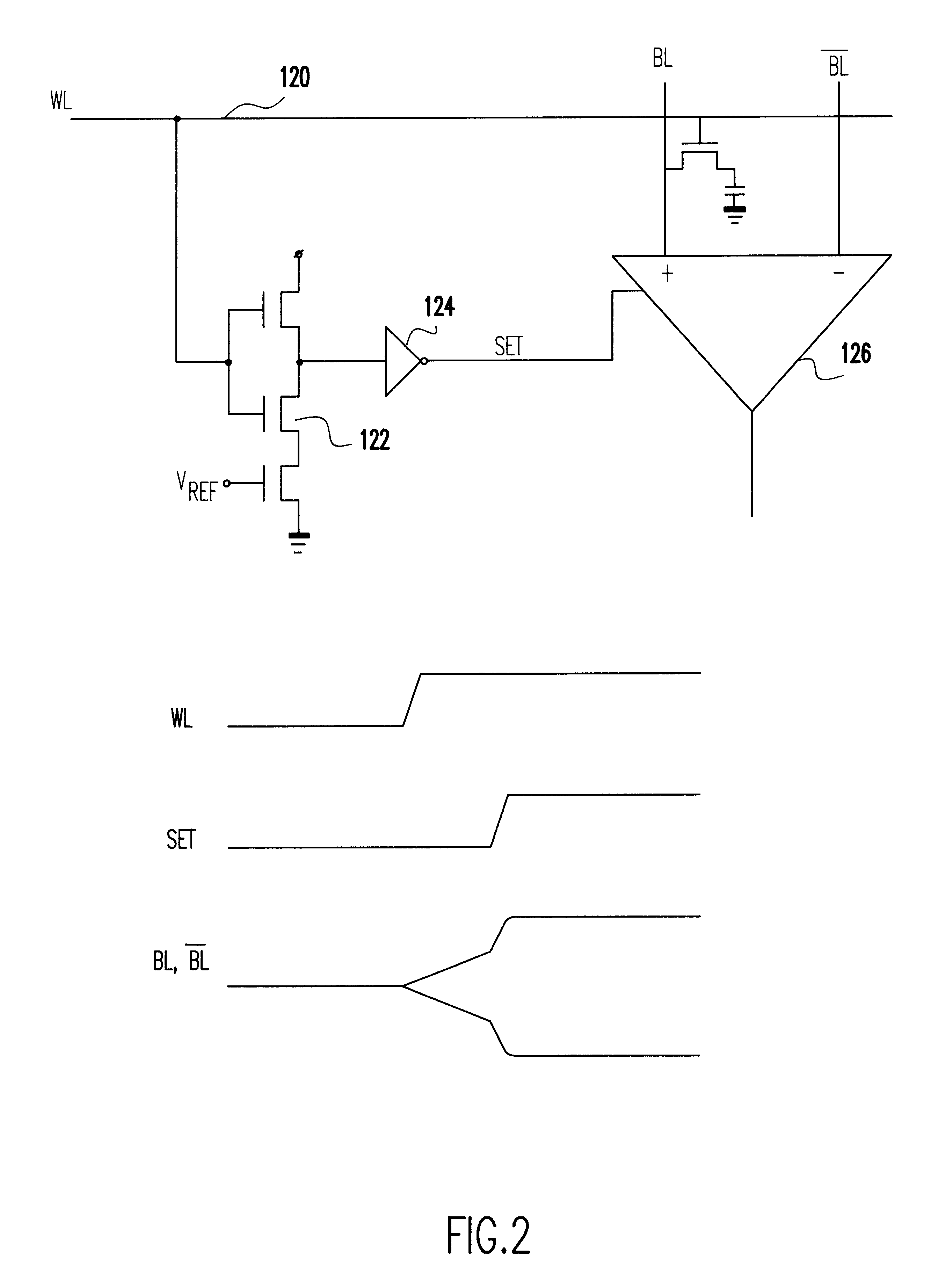
1. Field of the InventionThe present invention generally relates to Dynamic Random Access Memories (DRAMs) and, more particularly to DRAMs with Built In Self Test (BIST) Capability.2. Background DescriptionState of the art Dynamic Random Access Memories (DRAM) and logic chips, such as microprocessors, may include Built In Self Test (BIST) capability. The BIST logic tests the DRAM or logic according to predefined tests to uncover any defective array elements.Such a state of the art logic and DRAM is designed to function at what are defined to be worst case conditions. Normally, such a conservative worst case design includes some design margin to assure functionality that limits the microprocessor's or DRAM's actual performance to something less than the its full capability. Design margin verses performance is a trade off that designers must make at design to maximize chip manufacturing yield and guarantee chip functionality to specification.Consequently, even though such a chip may i...

Claims


Application Information

Patent Timeline
IPC IPC(8): G11C7/20G11C7/00G11C11/407G11C11/4072G11C29/02G11C29/50G11C29/04G01R31/28G11C11/401G11C29/12
CPCG11C7/20G11C11/4072G11C29/02G11C29/026G11C29/028G11C29/50G11C29/50012G11C11/401G11C2029/5004G11C2207/2254
Inventor KIRIHATA, TOSHIAKIWAIT, CHRISTOPHER DOUGLAS
Owner IBM CORP
Learn More