Machine tool for machining cavities in workpieces

a technology for workpiece cavities and machine tools, which is applied in the field of machine tools, can solve problems such as the inability to machine the cavity of workpieces, the loss of valuable machining time, and the internal hollowness of bell-shaped workpieces

Inactive Publication Date: 2001-02-06
CHIRON WERKE
View PDF27 Cites 9 Cited by
  • Summary
  • Abstract
  • Description
  • Claims
  • Application Information

AI Technical Summary

Problems solved by technology

In this connection, problems occur with internally hollow, for example bell-shaped workpieces, whose interior must be machined with a tool that, for reasons relating either to design or to clamping technology, cannot be introduced into the workpiece cavity from above.
To allow this machining in the interior of the workpiece to be accomplished, the workpiece must thus be reclamped, causing valuable machining time to be lost.
This eliminates the reclamping that would otherwise be necessary; it is now also possible to machine workpiece cavities of workpieces which do not have correspondingly large openings even on their underside, so that even a reclamping would not make it possible to machine the workpiece cavity.
Large lateral openings of this kind can cause stability problems in the workpiece, and should therefore be as small as possible.
It is clear that manipulations of this kind with adapter tools and machining tools interfere with the normal machining sequence of an otherwise fully automatic machine tool: they considerably reduce workpiece throughput during the machining of such workpieces, and moreover represent a safety risk to the operator.
Although the new changing mechanism requires a considerable design outlay and results in appreciable costs, this is, amazingly, more than compensated for by the structural advantages that can be attained in the workpiece being machined, and by the considerably elevated machining rate.
This means, however, that the lateral space necessary upon introduction of the machining tool through the lateral opening into the workpiece cavity is only slightly greater than that corresponding to the width of the machining tool.
If the machining tool remains behind in the gripper hand when the latter is pulled back, this represents a malfunction which is also reported.

Method used


Image

  • Machine tool for machining cavities in workpieces
  • Machine tool for machining cavities in workpieces
  • Machine tool for machining cavities in workpieces

Examples


Embodiment Construction

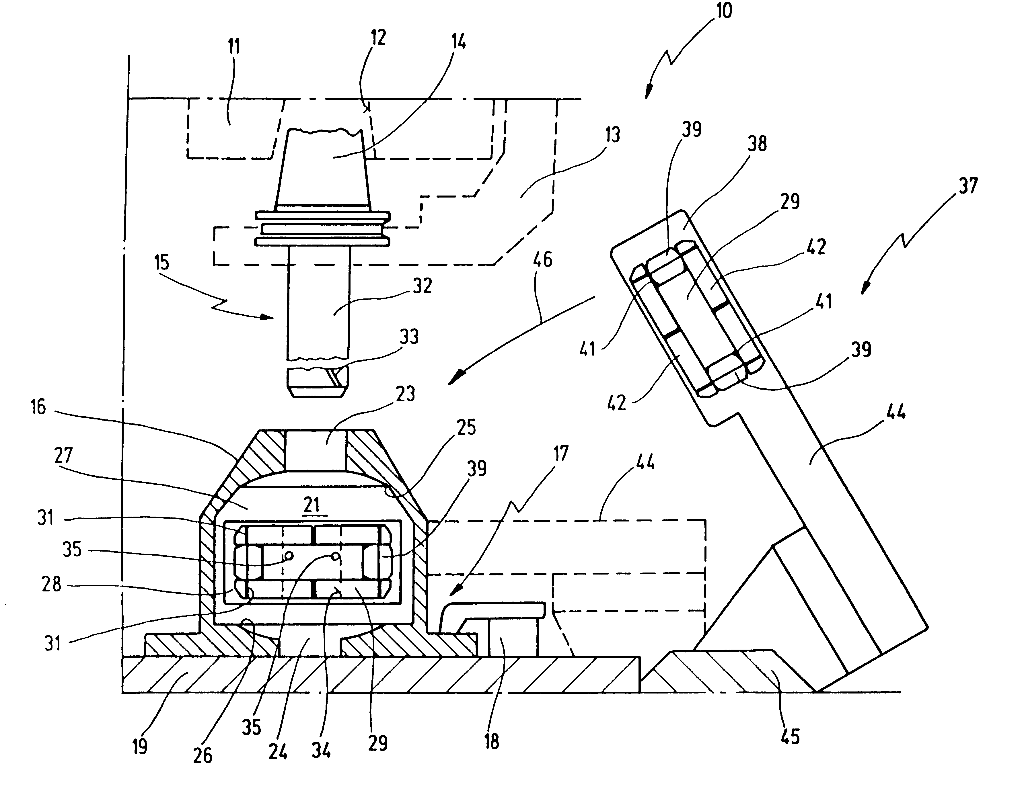
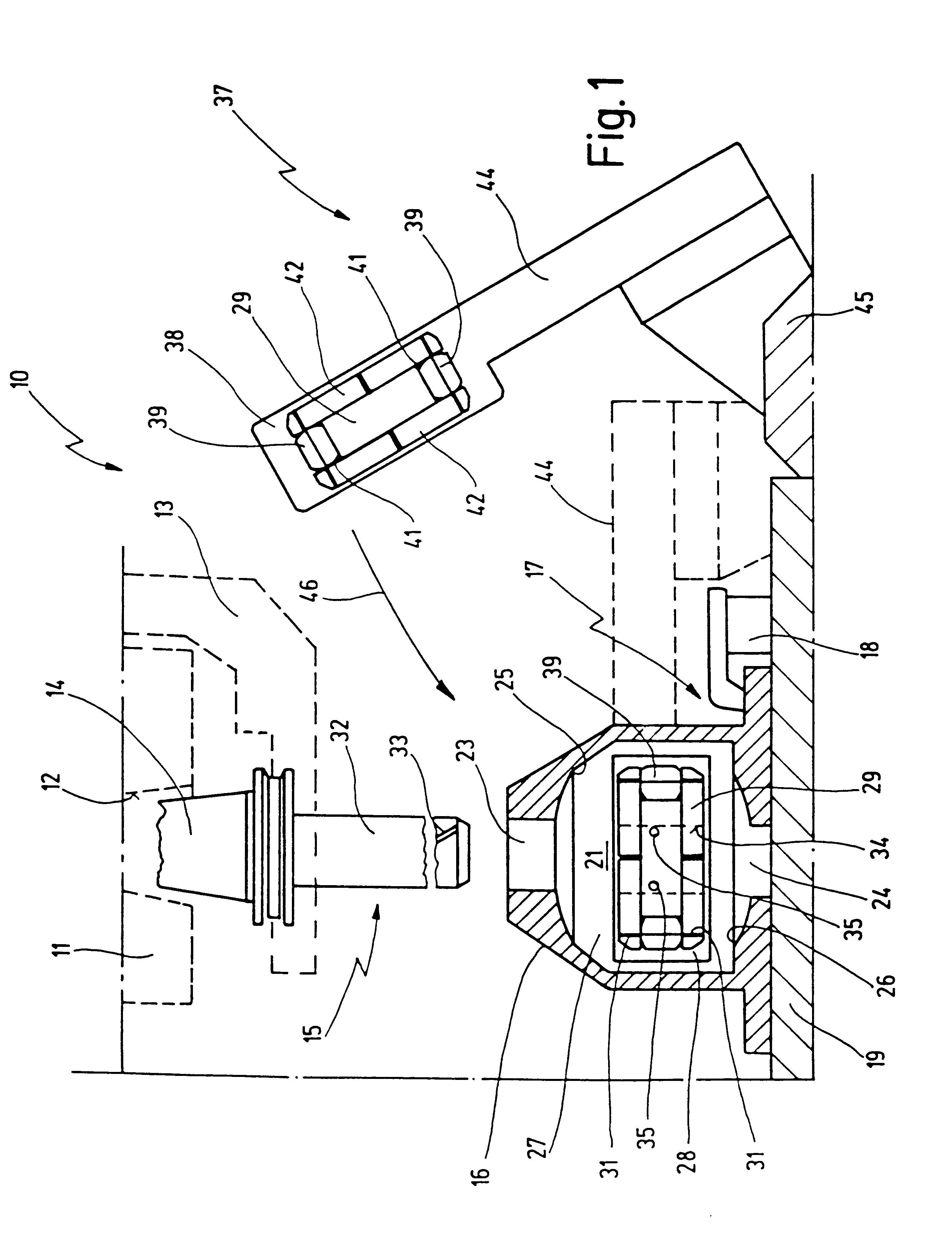
In FIG. 1, 10 very schematically indicates a machine tool which comprises a spindle (indicated at 11) in which a tool receptacle (indicated at 12) is provided. Machine tool 10 further has a schematically drawn tool changer 13.

Tool changer 13 holds a standardized tool holder 14 which can be inserted into tool receptacle 12. Provided on tool holder 14 is a tool 15 which serves to machine a workpiece 16 that is clamped on a mechanism indicated at 17. Mechanism 17 comprises, for example, clamping claws of which one is indicated at 18, as well as a cradle plate 19 on which workpiece 16 rests.

Workpiece 16 is shown in section in FIG. 1, thus making visible its workpiece cavity 21 into which a bore 23 leads from above and a bore 24 leads from below. The transition between workpiece cavity 21 and bore 23 or 24 is constituted by an edge 25 or 26 that is to be machined. Because the diameters of bores 23 and 24 are relatively small, the tool required for this machining operation cannot be intro...


PUM


Abstract

A machine tool (10) has a spindle (11) for receiving a tool (15) for machining a workpiece (16). A mechanism (17) for clamping the workpiece (16) is also provided. Also provided is a changing mechanism (37) for a machining tool (29), which holds the machining tool (29) in a gripper hand (38) which it introduces laterally into a workpiece cavity (21) in such a way that it can be automatically coupled there to an adapter tool (32) carried by the spindle (11).

Description

1. Field of the InventionThe present invention relates to a machine tool having a spindle for receiving a tool for machining a workpiece, and a mechanism for clamping the workpiece.2. Related Prior ArtMachine tools of this kind are commonly known from the prior art.Machine tools of this kind generally have tool changing mechanisms with which tools attached to standardized tool holders can be transferred between a tool receptacle in the spindle and a magazine position. In this manner, with a single workpiece clamping, different machining operations using different tools can be performed in succession on the clamped workpiece before it is replaced with a workpiece yet to be machined.With machine tools of this kind, a very rapid tool change is desirable so as to minimize the time necessary for the machining occurring in one clamping, so that the machine tool's workpiece throughput is high.A basic prerequisite for machining a workpiece using a tool clamped in the spindle is of course th...

Claims


Application Information

Patent Timeline
Patent Type & Authority Patents(United States)
IPC IPC(8): B23Q3/18B23Q3/157B23C5/00B23C1/00
CPCB23Q3/157B23Q3/15713B23Q3/18Y10S483/90Y10T483/10Y10T483/1752Y10T483/136Y10T483/13Y10T483/15Y10T483/19Y10T483/1736
Inventor DEUFEL, KARL
Owner CHIRON WERKE
Why Eureka
Try Eureka