
Electrochromic devices

Inactive Publication Date: 2001-01-23
DONNELLY CORP
View PDF21 Cites 817 Cited by
  • Summary
  • Abstract
  • Description
  • Claims
  • Application Information

AI Technical Summary

Benefits of technology

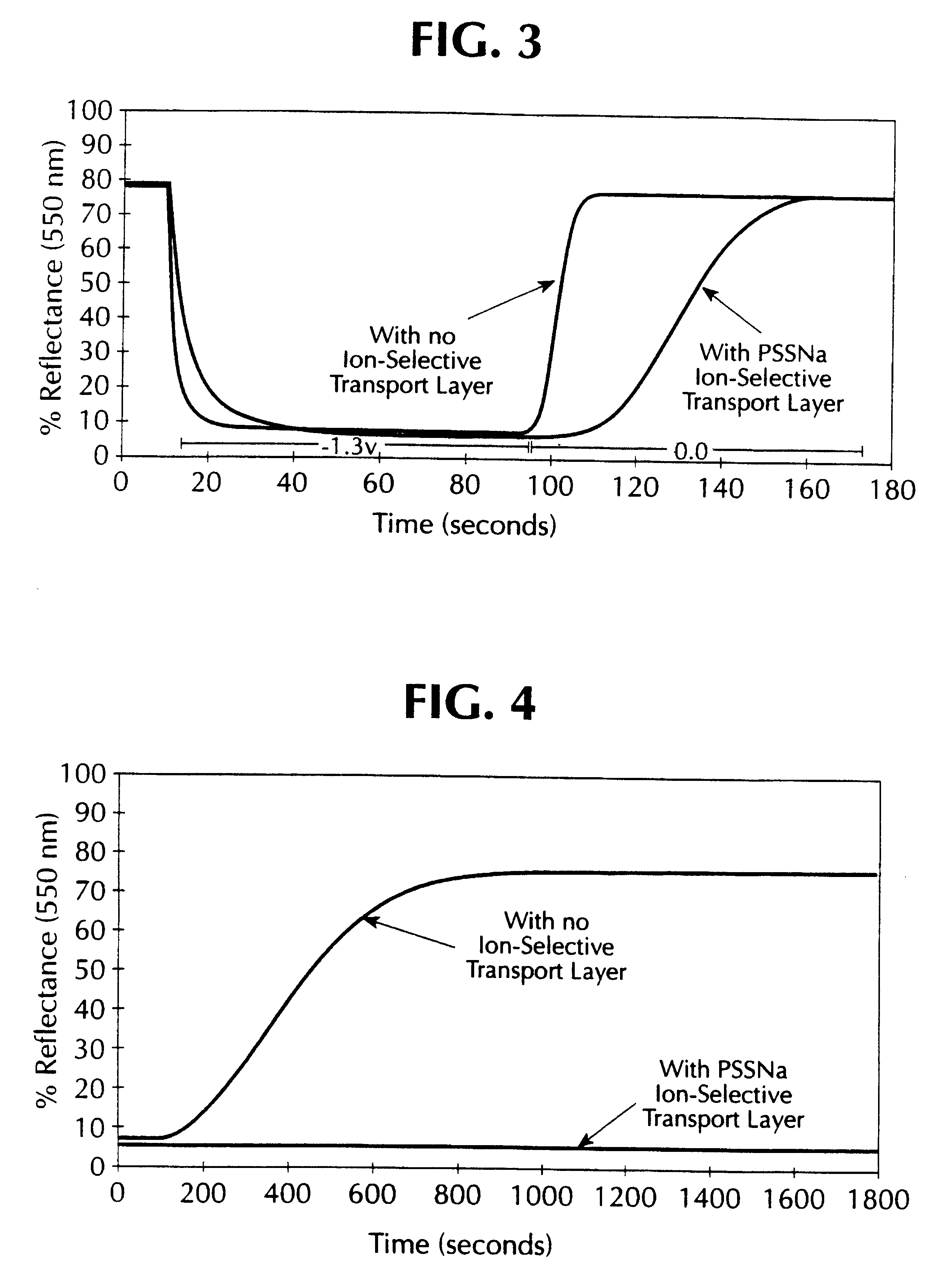
The EC devices of this invention are particularly advantageous for use as large area architectural and automotive glazings which benefit from the inhibition of back reaction, and thus can be activated to a low transmissive state without the requirement of continuous electrical stimulation to maintain that state of low transmission.
These EC devices may also be used as displays having an advantageously wide viewing area with a high contrast because no polarizers are required as in conventional liquid crystal displays In addition, EC display devices having an ion selective transport layer do not require continuous power to continually display a constant image, unlike liquid crystal devices and EC devices lacking memory. Power is only necessary when the display information needs to be changed. Thus, an EC display device of this invention may be advantageously employed in such applications as price displays in supermarkets, gas stations, instruments and the like with the benefit of reduced power consumption.

Problems solved by technology

Indeed, if the back reaction is significant, then with increasing area of the device it is more difficult to maintain a uniform transmissive state, e.g., uniform coloration, over the entire area of such a device.
Because of these requirements, the assembly of such EC devices is generally cumbersome and expensive.
This publication does not disclose an electrolyte layer containing a redox active material and thus requires rather large voltage applications which are deleterious to the long term stability of an EC device.

Method used


Image

  • Electrochromic devices
  • Electrochromic devices
  • Electrochromic devices

Examples


example 1

Ta.sub.2 O.sub.5 Overcoated WO.sub.3 Electrode and Ferrocene Electrolyte

A similar device was made as described in comparative example 1, but the WO.sub.3 electrode was overcoated with a thin film of tantalum (V) oxide (Ta.sub.2 O.sub.5). The Ta.sub.2 O.sub.5 precursor solution was prepared by dissolving 1.3 milliliters of tantalum ethoxide in 30 milliliters of dry ethanol and 1.13 milliliters of 2,4-pentanedione as a complexing agent. This solution was stirred under an inert atmosphere for two hours. To this solution was added 0.06 milliliters of one normal (1N) hydrochloric acid and 0.034 milliliters of deionized water. This solution was stirred under nitrogen for two hours prior to use. The solution was then spin coated onto a transparent WO.sub.3 coated tin oxide glass substrate. The Ta.sub.2 O.sub.5 overcoat (selective ion transport layer) was cured at room temperature in an atmosphere of 50% relative humidity for 12 hours. The device was then assembled as described in comparati...

example 2

LiNbO.sub.3 overcoated WO.sub.3 Electrode and Ferrocene Electrolyte

A similar device was made as described in comparative example 1, but the WO.sub.3 electrode was overcoated with a thin film of LiNbO.sub.3. The LiNbO.sub.3 precursor solution was prepared by the addition of 0.8 milliliters of 2,4-pentanedione to dry ethanol followed by 3.0 milliliters of niobium ethoxide. This solution was stirred under dry nitrogen for approximately 3 hours. Then 1.2 grams of lithium 2,4-pentanedionate dissolved in 24 milliliters of dry methanol was added. The solution was stirred under nitrogen and filtered through a 0.5 micron Millipore filter. The solution was spin coated onto a transparent WO.sub.3 coated tin oxide glass substrate. The thickness of the LiNbO.sub.3 coating was between 500 to 600 angstroms. The coating was cured at room temperature. The device was then assembled as described in comparative example 1. The performance of the device was as follows:

When a potential of +1.3 V was appli...

example 3

SiO.sub.2 Thin Film Overcoated on WO.sub.3 Electrode and Ferrocene Electrolyte

A similar device was made as described in comparative example 1, except that the WO.sub.3 electrode was overcoated with a thin film of SiO.sub.2. The SiO.sub.2 overcoat was deposited by spin coating with a 1 volume percent solution of tetraethoxysilane in dry ethanol. The overcoated WO.sub.3 electrode was cured at room temperature prior to assembling into a cell as described in comparative example 1. The performance of the device was as follows:

When a potential of +1.3 V was applied to the device (the negative lead being connected to the WO.sub.3 coated electrode), its transmittance (measured at 550 nm) changed from 77% T to 11% T in about 90 seconds. The current in the colored state was 7.39 mA for an area of 45.5 cm.sup.2 (162 .mu.A / cm.sup.2). When the power source was disconnected, its transmission went back from 11% T to 41% T in about 120 seconds. When shorted in the colored mode the cell went from 11...


PUM


Abstract

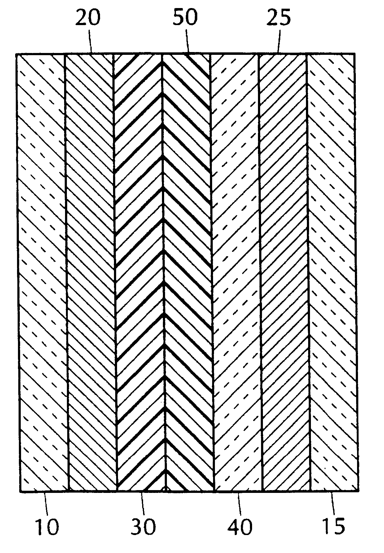
An electrochromic device is disclosed having a selective ion transport layer which separates an electrochemically active material from an electrolyte containing a redox active material. The devices are particularly useful as large area architectural and automotive glazings due to there reduced back reaction.

Description

1. Field of the InventionThis invention relates to electrochromic (EC) devices which can vary the transmission or reflectance of electromagnetic radiation by application of an electrical stimulus to the EC device. In particular, the EC devices of this invention employ a selective ion transport layer in combination with an electrolyte containing at least one redox active material to provide excellent device response and stability.2. Related Prior ArtElectrochromic devices are well known. Such devices are described, for example, in U.S. Pat. No. 4,435,408 (an electrochromic device comprising a pair of transmissive electrodes having disposed therebetween an electrochromic material and an electrolyte layer containing a non-liquid material of an adhesive or tacky high polymer and a material having a coordinating function); GB2268595 (an electrochromic device comprised of a substrate bearing an electrode followed by an electrochromic layer, an electrolyte layer containing a cation doner m...

Claims


Application Information

Patent Timeline
IPC IPC(8): G02F1/01G02F1/15G02F1/153G02F1/1503
CPCG02F1/1521G02F1/1525G02F2001/1536G02F1/1503
Inventor ALLEMAND, PIERRE M.GRIMES, RANDALL F.INGLE, ANDREW R.CRONIN, JOHN P.KENNEDY, STEVE R.AGRAWAL, ANOOPBOULTON, JONATHAN M.
Owner DONNELLY CORP
Learn More