
Frequency multiplying transceiver

a transceiver and frequency technology, applied in the field of frequency multiplication transceivers, can solve the problems of high jitter and phase noise of signals provided at the output of each delay element, injection may also undesiredly introduce asymmetry in the phases of oscillation signals, and undesirable effects of asymmetries, etc., to achieve low power transmission, low weight, and small size

Inactive Publication Date: 2014-08-19
UNIV OF WASHINGTON CENT FOR COMMERICIALIZATION
View PDF13 Cites 9 Cited by
  • Summary
  • Abstract
  • Description
  • Claims
  • Application Information

AI Technical Summary

Benefits of technology

This patent describes methods, systems, and devices that allow small and light wireless devices to transmit and receive wireless communications with low power. These methods avoid using high-frequency frequency synthesis and modulation, which can dramatically reduce power consumption. They also use edge combination to reduce power consumption in both transmission and receipt functions. Overall, this patent provides a way for small wireless devices to communicate wirelessly with low power.

Problems solved by technology

While ring oscillators are generally characterized by low power consumption, the signals provided at the output of each delay element may exhibit high jitter and phase noise.
However, such a direct, single phase, injection may also undesirably introduce asymmetry in the phases of the oscillation signals.
Such asymmetries may have undesirable effects when combining the oscillation signals.
For instance, such asymmetries may lead to large reference spurs in such a combined signal.
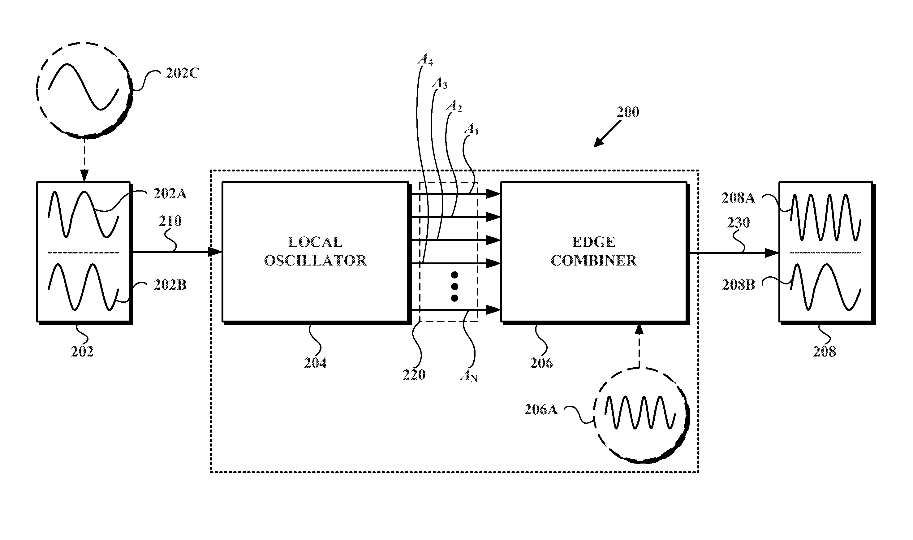
On the other hand, the addition of such further phase injections (and / or injection stages) may require the expenditure of additional power and may introduce additional noise into transceiver 200.
Generally, data modulation techniques that involve synthesis of high-frequency signals for modulation at such high frequencies, such as carrier frequencies, are power intensive.

Method used


Image

  • Frequency multiplying transceiver
  • Frequency multiplying transceiver
  • Frequency multiplying transceiver

Examples


Embodiment Construction

[0026]In the following detailed description, reference is made to the accompanying figures, which form a part thereof in the figures, similar symbols typically identify similar components, unless context dictates otherwise. The illustrative embodiments described in the detailed description, figures, and claims are not meant to be limiting. Other embodiments may be utilized, and other changes may be made, without departing from the spirit or scope of the subject matter presented herein. It will be readily understood that the aspects of the present disclosure, as generally described herein, and illustrated in the figures, can be arranged, substituted, combined, separated, and designed in a wide variety of different configurations, all of which are explicitly contemplated herein.

I. INTRODUCTION

[0027]Described herein are aspects of a frequency-multiplying wireless transceiver that may be arranged, generally, to provide for both low-power transmission and low-power reception of wireless ...


PUM


Abstract

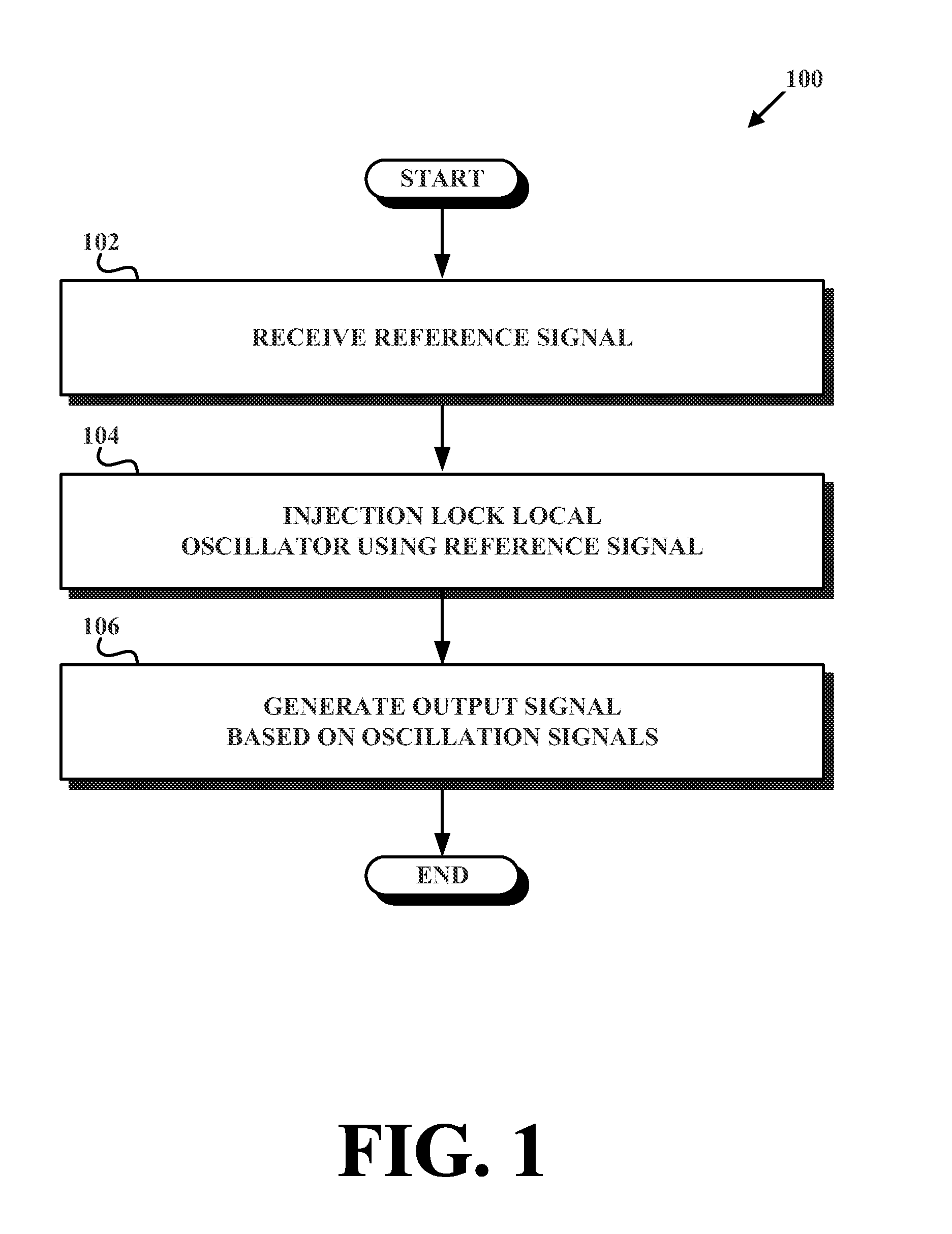
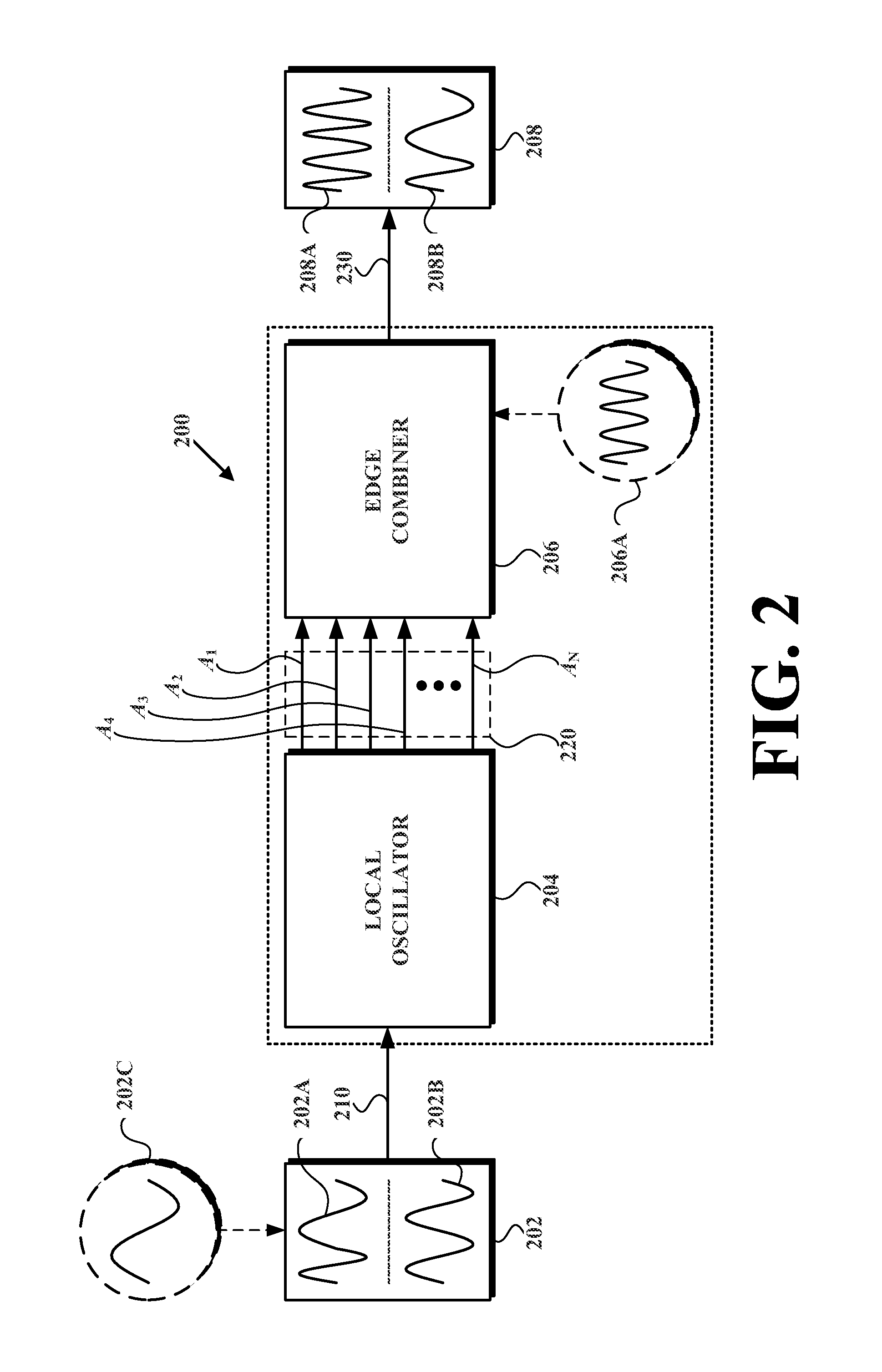
Described herein is a wireless transceiver and related method that enables ultra low power transmission and reception of wireless communications. In an example embodiment of the wireless transceiver, the wireless transceiver receives a first-reference signal having a first-reference frequency. The wireless transceiver then uses the first-reference signal to injection lock a local oscillator, which provides a set of oscillation signals each having an oscillation frequency that is equal to the first-reference frequency, and each having equally spaced phases. Then the wireless transceiver combines the set of oscillation signals into an output signal having an output frequency that is one of (i) a multiple of the first-reference frequency (in accordance with a transmitter implementation) or (ii) a difference of (a) a second-reference frequency of a second-reference signal and (b) a multiple of the first-reference frequency (in accordance with a receiver implementation).

Description

RELATED APPLICATIONS[0001]This application claims priority to: U.S. Provisional Patent Application Ser. No. 61 / 316,784, entitled Frequency Multiplying Transceiver, filed Mar. 23, 2010; U.S. Provisional Patent Application Ser. No. 61 / 316,790, entitled Frequency Multiplying Transceiver, filed Mar. 21, 2010; and U.S. Provisional Patent Application Ser. No. 61 / 410,176, entitled Frequency Multiplying Transceiver, filed Nov. 4, 2010 all of which are incorporated by reference herein in their entirety.BACKGROUND[0002]Generally, wireless transceivers may be severely energy constrained as a result of, among other things, running off a small battery and / or energy scavenging techniques. Thus as wireless-communication technologies have become more and more pervasive over recent years, so too has the demand for ultra-low power (ULP) wireless transceivers. ULP wireless transceivers have many applications including, as a few examples, as wireless-sensor networks (which may monitor, e.g., geographic...

Claims


Application Information

Patent Timeline
Patent Type & Authority Patents(United States)
IPC IPC(8): H04B1/06H04B7/00
CPCG06F7/68H04B1/16H03C3/00H03K5/00006H03D3/00H04B1/38H03K3/0315H03L7/24
Inventor OTIS, BRIAN PATRICKPANDEY, JAGDISH NARAYAN
Owner UNIV OF WASHINGTON CENT FOR COMMERICIALIZATION
Learn More