
System and method for refining sugar

a technology of sugar refining and system, applied in the field of sugar refining, can solve the problems of reducing the supply of carbon dioxide, reducing the efficiency of sugar refining process, and correspondingly limited plant operation, so as to improve the efficiency and throughput improve the efficiency and improve the effect of sugar refining process

Inactive Publication Date: 2001-01-23
AIR LIQUIDE AMERICA INC +1
View PDF2 Cites 20 Cited by
  • Summary
  • Abstract
  • Description
  • Claims
  • Application Information

AI Technical Summary

Benefits of technology

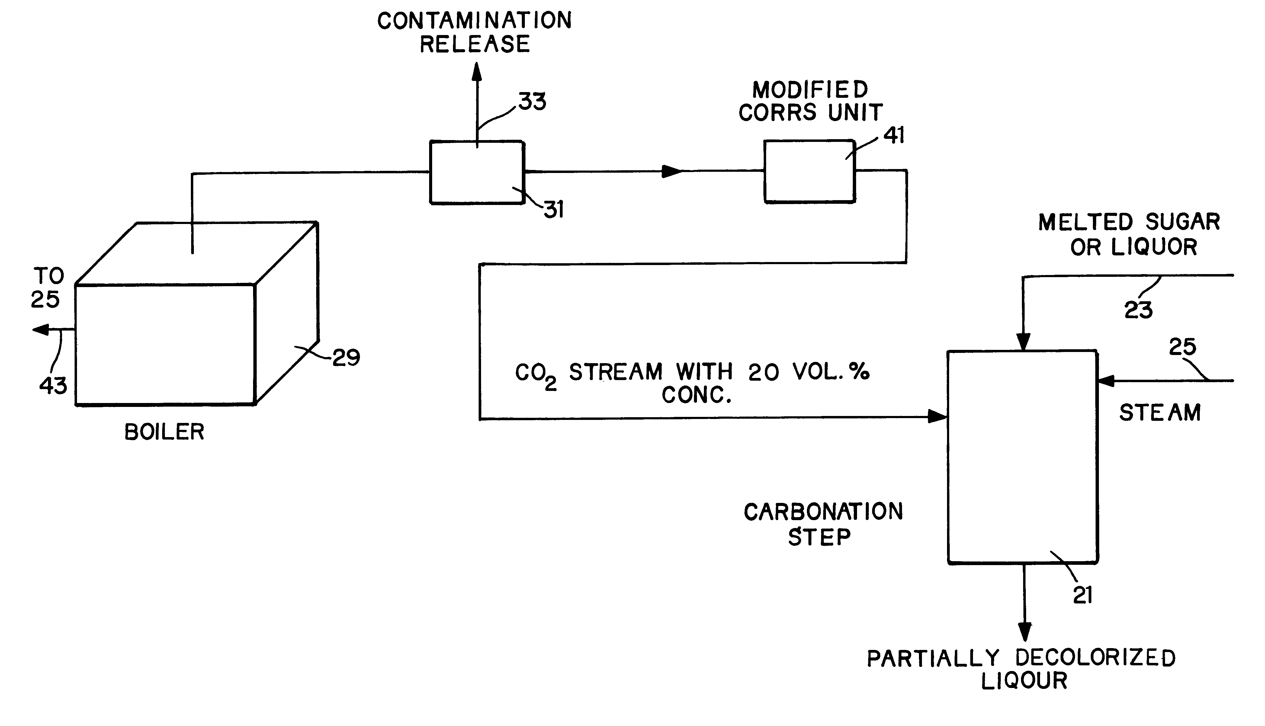
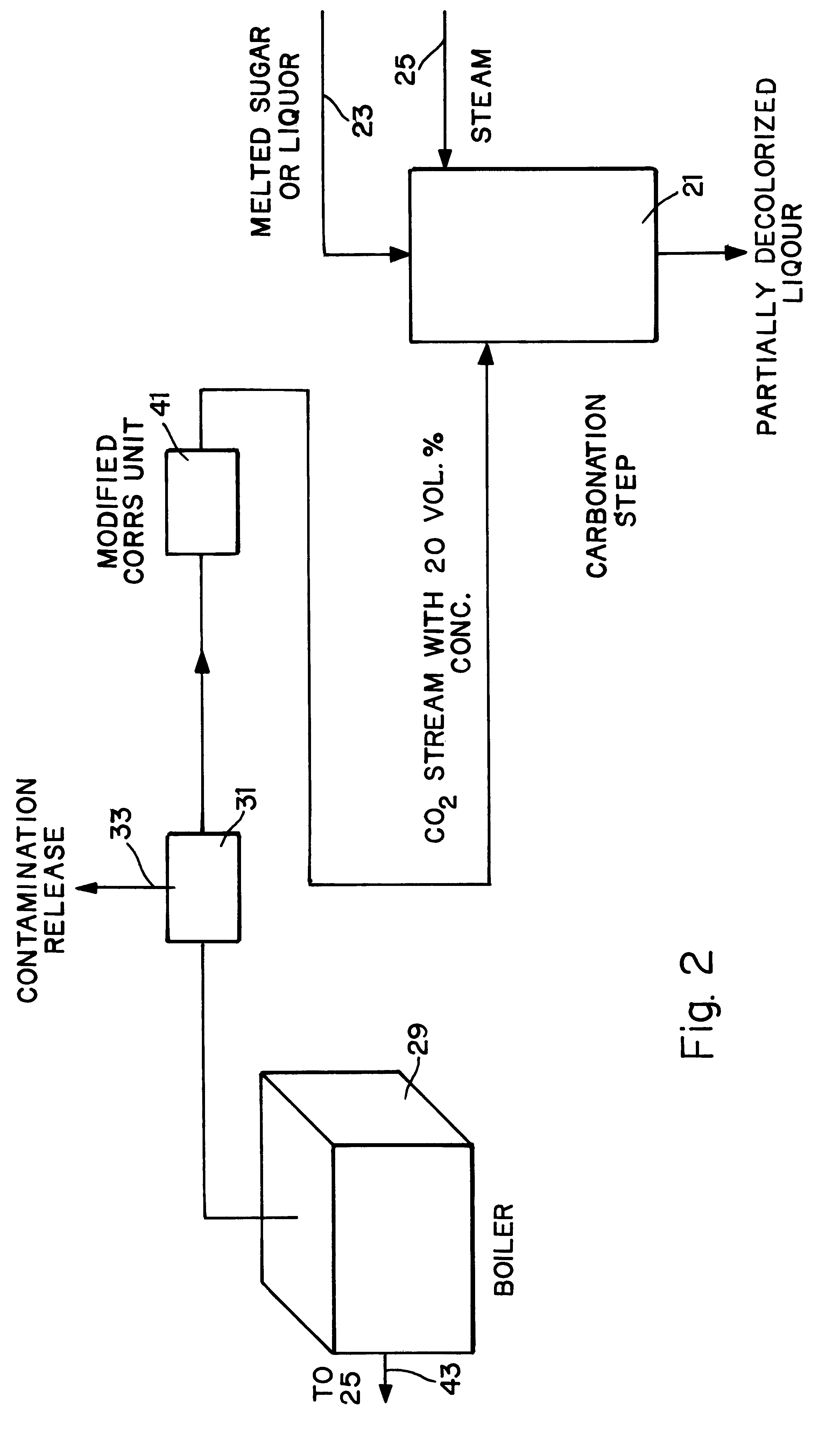
In the preferred embodiment, the boiler used as the source of carbon dioxide is the same boiler used to produce steam which drives the reaction. Thus, the present invention uses exhaust from an already existing boiler, and efficiently converts that exhaust into a usable source of carbon dioxide.
The invention has the further object of minimizing interruptions to production in a sugar refining plant, by providing a steady and reliable source of carbon dioxide.

Problems solved by technology

If the supply of carbon dioxide is curtailed, the entire operation of the plant is correspondingly limited.
The major disadvantage of using the boiler exhaust as a source of carbon dioxide is that if a problem with the boiler develops, it may be necessary to reduce the boiler output.
In the latter case, the supply of carbon dioxide is thereby reduced, thus affecting the operation of the entire plant.
But providing such backup, which could require storage of large tanks of compressed gas or liquefied gas, is inconvenient and expensive.
While the latter system works, it is expensive, as it requires the additional steps of handling chemicals.
Moreover, most existing installations do not have the capability of processing sugar rapidly enough to justify the use of pure carbon dioxide.
Thus, for most sugar refineries, the use of pure carbon dioxide would be unduly expensive relative to the benefit conferred.

Method used


Image

  • System and method for refining sugar
  • System and method for refining sugar
  • System and method for refining sugar

Examples


Embodiment Construction

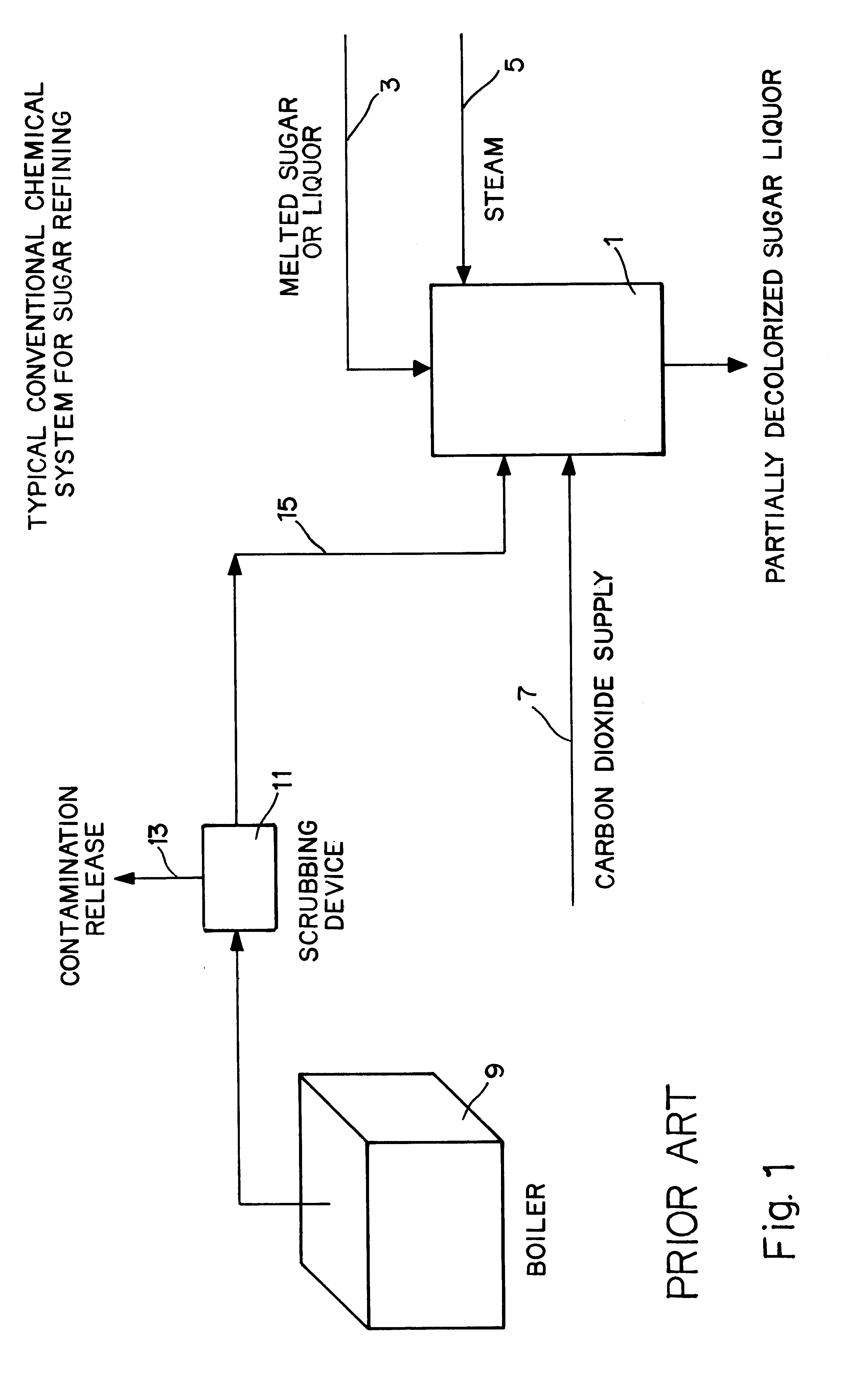
FIG. 1 shows a typical sugar refining system of the prior art. This figure does not purport to depict all of the steps in a sugar refining process; the present invention is concerned only with the carbonation step, described above.

The carbonation process takes place in reactor 1. Melted sugar, also known in the art as liquor, enters the reactor through line 3. This is the unrefined sugar which has a light brown color. Steam is injected into the reactor through line 5. Carbonation is accomplished with carbon dioxide which is derived primarily from the exhaust gas of boiler 9. The boiler is used to heat water to provide the steam which enters the reactor in line 5, thereby heating the contents of the reactor.

The exhaust gas is purified in scrubber 11, which removes particulates and other impurities, as symbolized by arrow 13. If the fuel used by the boiler is natural gas, the output of the scrubber comprises a stream having about 6-9% carbon dioxide, by volume. This stream is carried ...


PUM

PropertyMeasurementUnit
Percent by volumeaaaaaaaaaa
Concentrationaaaaaaaaaa

Abstract

A sugar refining process uses carbon dioxide obtained from a module containing a plurality of gas-permeable polymeric membranes. Flue gas from a boiler is scrubbed, and then passed through the gas-separation module. The output of the module contains an enhanced concentration of carbon dioxide, in the range of about 20% by volume. The carbon dioxide enhanced gas is then directed into a reactor in which raw sugar is exposed to carbon dioxide to cause carbonation, an essential step in the decolorization of the raw sugar. The same boiler used to produce the carbon dioxide is also used to produce steam which drives the reaction. The present invention provides carbon dioxide for carbonation in a highly efficient manner, as the gas separation membrane has no moving parts and requires little maintenance. The invention is especially suited for retrofitting existing sugar refining plants, to improve their efficiency, at a relatively small cost.

Description

BACKGROUND OF THE INVENTIONThe present invention relates to the field of sugar refining, and provides a system and method which improves the efficiency of the refining process.Raw sugar is obtained by extracting the juice from sugar cane, and processing the juice to produce sugar crystals. The raw sugar is light brown in color, due to the presence of color bodies in the crystals. The color of the crystals is determined by the content of organic chemicals in the sugar. A primary object of the refining process is to convert the raw, brown sugar into white sugar.A major component of the sugar refining process is known as carbonation. In the carbonation step, carbon dioxide is added to raw sugar which has been dissolved to form a clarified liquor. The carbon dioxide reacts with calcium in the sugar to form calcium carbonate (CaCO.sub.3). The calcium carbonate precipitates out of the sugar, and takes with it a large proportion of the color bodies. In fact, in a single carbonation step, m...

Claims


Application Information

Patent Timeline
IPC IPC(8): C13D3/00C13D3/06C13B20/06C13B30/04C13B30/14
CPCC13B20/06
Inventor BRAHMBHATT, SUDHIR R.
Owner AIR LIQUIDE AMERICA INC
Learn More